background image

Intel® Server System M20MYP1UR System Integration and Service Guide


23 

6.


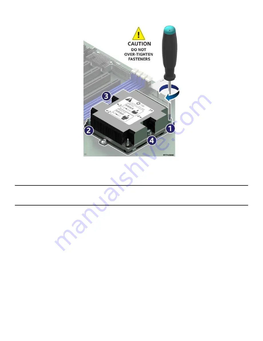
Secure PHM to the processor socket assembly. 


Figure 15. Installing the PHM 


Using a T30 Torx bit screwdriver, securely tighten (12 in-lbs.) each fastener in the sequence shown on 
the label located on the top of the heat sink. 

Caution

: Failure to tighten the heat sink screws in the specified order may cause damage to the processor 

socket assembly. Each heat sink screw should be fully tightened to 12 in-lbs. torque before securing the next 
screw in the sequence. 

7.


For a second procesor, repeat the processor installation instructions above, ensuring the proper 
processor heatsink and processor carrier clip are used for the installation.  

For single processor configurations where a 2

nd

 processor is not present, install the CPU 2 heat sink onto the 

CPU 2 socket without removing the processor socket cover  to ensure proper airflow when the system is 
operational.  


Summary of Contents for M20MYP1UR

Page 1: ...vation Experience What s Inside Intel Server System M20MYP1UR Integration and Service Guide A guide providing instructions for the insertion and extraction of system components and available Intel acc...

Page 2: ...Intel Server System M20MYP1UR System Integration and Service Guide 2 Blank page...

Page 3: ...Intel Server System M20MYP1UR System Integration and Service Guide 3 Document Revision History Date Revision Changes May 2020 1 0 First release...

Page 4: ...or otherwise to any intellectual property rights is granted by this document The products described may contain design defects or errors known as errata which may cause the product to deviate from pub...

Page 5: ...ake care when using needle nosed pliers to remove or install a jumper grip the narrow sides of the jumper with the pliers never the wide sides Gripping the wide sides can damage the contacts inside th...

Page 6: ...user notices in the product user guide and specification documents may result in loss of or access to data Weight of the system Due to the weight of a system Intel recommends carrying the system with...

Page 7: ...SD into a 3 5 Drive Carrier Assembly 31 3 Option and Accessory Kit Integration and Service 34 3 1 Internal Cable Routing Channels 35 3 2 PCIe Add in Card Removal Installation 36 3 2 1 Riser Card Brack...

Page 8: ...tel Management Engine Intel ME Firmware Force Update Jumper Block 58 6 2 4 BMC Force Update Jumper Block 59 6 2 5 BIOS Recovery Jumper 60 7 System Service FRU Replacement 61 7 1 Replacing a Power Supp...

Page 9: ...5 Figure 19 Releasing the processor carrier clip from the heat sink 25 Figure 20 Releasing processor from carrier clip 26 Figure 21 DIMM blank 26 Figure 22 System DIMM slot population requirements for...

Page 10: ...ification 54 Figure 53 Intel Light Guided Diagnostic LEDs server board 55 Figure 54 DIMM fault LEDs 56 Figure 55 System configuration and recovery jumpers 57 Figure 56 Power supply removal 62 Figure 5...

Page 11: ...Intel Server System M20MYP1UR System Integration and Service Guide 11 Table 9 Integrated BMC beep codes 91 Table 10 Server system references 105 Table 11 System utility software 105...

Page 12: ...part of the document Chapters 2 5 provides instructions on the installation of essential system components and available accessories as well as providing system firmware update instructions and syste...

Page 13: ...kits may be required Chapter 3 provides instructions to accomplish this Before You Begin Before working with your server product observe the safety and ESD precautions found in the Safety Warnings se...

Page 14: ...ts inside of the system Before removing the system cover power off the system and disconnect all peripheral devices and power cable Note A non skid surface or a stop behind the server system may be re...

Page 15: ...ntil it locks into place see Letter A Shipping note When transporting the server system Intel recommends installing the three top cover screws See Letter B prior to shipping 2 2 Air Duct Removal Insta...

Page 16: ...ut area to avoid interference from the cables during the air duct removal 3 Lift the air duct straight up and remove it from the system 2 2 2 Air Duct Installation Figure 4 Air duct installation 1 Ens...

Page 17: ...el Server Systems requires that the processor be attached to the heat sink prior to installation on to the server board The processor heat sink assembly is referred to as the processor heat sink modul...

Page 18: ...ion 2 Place the heat sink bottom side up on to a flat surface as shown above 3 If present carefully remove the plastic protective cover from the bottom side of the heat sink to expose the Thermal Inte...

Page 19: ...own in the above figure Figure 9 Processor clip sub assembly 7 Install the processor into the processor clip until it snaps into place CAUTION To prevent the processor from falling out of the clip the...

Page 20: ...the processor heat sink until it snaps into place ensuring all four corners are secure Processor clip sub assembly should sit flat on top of the heat sink 2 3 2 Processor Installation The Intel Serve...

Page 21: ...in the socket see Letter B Note The processor socket cover should be saved for future use Caution When re installing the socket cover make sure it properly snaps into place Improper installation will...

Page 22: ...TION Processor socket pins are delicate and bend easily Use extreme care when placing the PHM onto the processor socket do not drop it 5 The PHM assembly is properly installed when seated flat and eve...

Page 23: ...may cause damage to the processor socket assembly Each heat sink screw should be fully tightened to 12 in lbs torque before securing the next screw in the sequence 7 For a second procesor repeat the...

Page 24: ...orx bit screwdriver loosen each heat sink fastener in the sequence shown on the label located on the top of the heat sink see Letter A 2 Lift the PHM straight up from the server board until it is free...

Page 25: ...t sink and the processor clip assembly and gently twist until the bond between heat sink and the processor is broken Figure 19 Releasing the processor carrier clip from the heat sink 6 Unlatch the hoo...

Page 26: ...the Intel Server System M20MYP1UR Technical Product Specification Each installed processor provides six memory channels On the Intel Server System M20MYP1UR memory channels for each processor are lab...

Page 27: ...vice Guide 27 Figure 22 System DIMM slot population requirements for thermal compliance On the Intel Server System M20MYP1UR DIMM slots A2 B1 D2 and E1 of both CPU sockets need to be populated with a...

Page 28: ...ee Letter B 3 Insert the bottom edge of the DIMM into the slot see Letter C 4 When the DIMM is inserted push down on the top edge of the DIMM until the retaining clips snap into place see Letter D 5 M...

Page 29: ...nd Supplies Anti static wrist strap and conductive workbench pad recommended 2 5 1 Drive Carrier Extraction Figure 25 Extracting drive carrier from chassis 1 Remove the drive carrier from the chassis...

Page 30: ...ge of the left rail upwards see Letter A while at the same time pushing the drive or drive blank down away from the carrier see Letter B Figure 28 3 5 Drive carrier assembly drive installation to carr...

Page 31: ...ctive workbench pad recommended Phillips cross head screwdriver 2 bit Figure 29 3 5 Drive carrier assembly drive blank removal 1 Remove the drive blank from the carrier by holding the carrier assembly...

Page 32: ...de a bag containing four mounting screws Figure 32 3 5 Drive carrier to 2 5 SSD bracket mount bracket assembly to carrier 4 With the rear drive connector positioned towards the back of the drive carri...

Page 33: ...Server System M20MYP1UR System Integration and Service Guide 33 Figure 33 3 5 Drive carrier to 2 5 SSD bracket secure SSD to carrier 7 Using two screws secure the SSD to the carrier side rail see Let...

Page 34: ...ection at the beginning of this manual Tools and Supplies Needed Anti static wrist strap and conductive workbench pad recommended Phillips cross head screwdriver 2 bit Flat head screwdriver System Ref...

Page 35: ...through the cable channels along each side of the server board as shown in the following illustration When routing cables front to back no cable should be routed through the center of the system or in...

Page 36: ...he riser assembly Required Tools and Supplies Anti static wrist strap and conductive workbench pad recommended Phillips cross head screwdriver 2 bit 3 2 1 Riser Card Bracket Removal 1 Power off the sy...

Page 37: ...re the add in card to the riser card bracket see Letter D 3 2 3 Riser Card Bracket Assembly installation Figure 37 Riser card bracket assembly installation 1 Position the riser card s edge connector o...

Page 38: ...ting tabs in the back of the riser card bracket disengage from the chassis 3 2 5 PCIe Add in Card Removal from Riser Card Bracket Figure 39 Removing PCIe add In card from riser card bracket 1 Remove t...

Page 39: ...the system and disconnect the AC power cord 2 Remove the system top cover see Section 2 2 1 3 Remove the Intel ESRT2 RAID 5 Key from its packaging 4 Locate the key connector shown in the above figure...

Page 40: ...4 Skip this step if no PCIe add in cards are installed on riser 1 4 Remove the Intel RMM4 Lite key from its packaging 5 Locate the Intel RMM4 Lite connector on the server board between the first two P...

Page 41: ...ve the system top cover see Section 2 2 1 3 Locate the TPM module connector on the server board next to the DIMM slots 4 Remove the TPM module and the included standoff and screws from their packaging...

Page 42: ...tors and the bracket Figure 43 M 2 connector and bracket identification 3 6 1 Installing One M 2 Device Single Configuration Figure 44 Installing one M 2 SSD device 1 Power off the system and disconne...

Page 43: ...a Phillips cross head screwdriver 5 Attach the bracket to the M 2 device that will be installed on the top connector using the provided screw see Letter A 6 Slide the M 2 device that is to be installe...

Page 44: ...OS Setup Utility This section describes how to access and navigate the embedded F2 BIOS Setup utility This utility can be used to view and configure system settings that determine how the server opera...

Page 45: ...exit confirmation window is displayed and the user is asked whether changes can be discarded If No is selected and the Enter key is pressed or if the Esc key is pressed the user is returned to where t...

Page 46: ...s pressed or if the Esc key is pressed the user is returned to where they were before F9 was pressed without affecting any existing field values F10 Save and Exit Pressing the F10 key causes the follo...

Page 47: ...protective packaging system When reused all of the original packaging material must be used including both boxes and each inner packaging component In addition all inner packaging components MUST be r...

Page 48: ...rver System M20MYP1UR System Integration and Service Guide 48 1 Place two foam inserts into the inner box as shown noting foam insert orientation 2 Carefully wrap the system with the red EPE sheet and...

Page 49: ...l Server System M20MYP1UR System Integration and Service Guide 49 3 Carefully place the system into the shipping bag and tape the bag shut 4 Carefully lower the system into the inner shipping box as s...

Page 50: ...d heatsink on each 6 Place the processor clips and other accessories in the rear top foam insert 7 Place the printed documents on top of the system between the two top foam inserts 8 Fold the top flap...

Page 51: ...M20MYP1UR System Integration and Service Guide 51 9 Fold the top flaps of the outer box end flaps first followed by the side flaps 10 Tape the outer box using an H pattern across the center first fol...

Page 52: ...MYP1UR See Appendix G for related documents containing additional information of this product 6 1 System Feature Reference Diagrams This section provides a high level overview of the Intel Server Syst...

Page 53: ...em M20MYP1UR System Integration and Service Guide 53 6 1 2 Control Panel Features Figure 49 Control panel features 6 1 3 Back Panel Features Figure 50 Back panel features Figure 51 Power distribution...

Page 54: ...Intel Server System M20MYP1UR System Integration and Service Guide 54 6 1 4 Server Board Features Figure 52 Server board feature identification...

Page 55: ...Intel Server System M20MYP1UR System Integration and Service Guide 55 Figure 53 Intel Light Guided Diagnostic LEDs server board...

Page 56: ...Intel Server System M20MYP1UR System Integration and Service Guide 56 Figure 54 DIMM fault LEDs...

Page 57: ...tings Note This jumper does not reset Administrator or User passwords To reset passwords the Password Clear jumper must be used 1 Power down the server and disconnect the AC power cord 2 Remove the sy...

Page 58: ...should be logged 5221 Passwords cleared by jumper 5224 Password clear jumper is set 7 Exit the BIOS Setup utility and power down the server For safety remove the AC power cord 8 Remove the system top...

Page 59: ...SUP posted to Intel s Download center web site http downloadcenter intel com 1 Download the SUP and unzip the contents copying them to the root directory of a FAT32 formatted removable media device US...

Page 60: ...can be downloaded from Intel s download center web site http downloadcenter intel com 1 Download the SUP and unzip the contents copying them to the root directory of a FAT32 formatted removable media...

Page 61: ...isconnected from the server system Before You Begin Before working with your server product observe the safety and ESD precautions found in the Warnings section at the beginning of this manual Require...

Page 62: ...be powered OFF before removing the power supply module Figure 56 Power supply removal 1 Detach the power cord from the power supply 2 Push and hold the green latch in the direction shown see Letter A...

Page 63: ...speeds Do not attempt to replace a system fan until it has stopped completely Attempting to remove a fan that is not completely stopped may result in injury Figure 58 System fan assembly removal 1 Po...

Page 64: ...ement fan in the fan assembly ensuring all rubber guides are in place and the cable is located on the side closest to the server board 7 Attach the fan cable to the fan connector on the server board E...

Page 65: ...type recommended by the equipment manufacturer Discard used batteries according to manufacturer s instructions Advarsel Lithiumbatteri Eksplosionsfare ved fejlagtig h ndtering Udskiftning m kun ske me...

Page 66: ...7 Remove the new lithium battery from its package and being careful to observe the correct polarity insert it into the battery socket Note The F2 BIOS Setup Utility must be accessed and the setting m...

Page 67: ...ver by sliding it up and then to the back of the chassis see Letter B 7 4 2 Installing the Backplane Figure 63 Installing the backplane 1 Locate the replacement 1U backplane 2 Hold the backplane only...

Page 68: ...all externally attached cables 3 Remove the chassis top cover see Section 2 1 1 4 Remove the air duct see Section 2 2 1 5 Disconnect all cables attached to PCIe add in cards if installed 6 Remove all...

Page 69: ...t 2 Carefully lower the server board into the chassis see letter A 3 Align the rear I O connectors of the board NIC connectors USB connectors and VGA connector with the IO shield openings and slide th...

Page 70: ...sis accessory parts list for ordering upgrades or spare parts A searchable knowledgebase to search for product information throughout the support site If you are still unable to obtain a solution to y...

Page 71: ...Intel Server System M20MYP1UR System Integration and Service Guide 71 Appendix B System Cable Routing Diagrams Figure 66 Intel Server System M20MYP1UR cable routing...

Page 72: ...te BIOS Status Description Front Status LED State Rear Status LED State System is not operating No AC power Stand by power present System is in S5 soft off state Off Off System is operating normally S...

Page 73: ...stem has failed or shut down Processor CATERR signal asserted MSID mismatch detected CATERR also asserts for this case CPU 1 is missing Processor Thermal Trip No power good power fault DIMM failure wh...

Page 74: ...ause of the hang condition Each POST code is represented by eight LEDs four green and four amber The POST codes are divided into two nibbles an upper nibble and a lower nibble The upper nibble bits ar...

Page 75: ...R4 frequency Lower 0 0 0 1 B2 Upper 1 0 1 1 Gather remaining Serial Presence Detection SPD data Lower 0 0 1 0 B3 Upper 1 0 1 1 Program registers on the memory controller level Lower 0 0 1 1 B4 Upper 1...

Page 76: ...1 0 No Usable Memory Error 01h No memory was detected via SPD read or invalid config that causes no operable memory 02h Memory DIMMs on all channels of all sockets are disabled due to hardware memtes...

Page 77: ...0 0 SEC core at power on begin Lower 0 1 0 1 06 Upper 0 0 0 0 Early CPU initialization during SEC phase Lower 0 1 1 0 Intel Ultra Path Interconnect Intel UPI RC Fully leverage without platform change...

Page 78: ...type initialization Lower 0 1 0 1 19 Upper 0 0 0 1 Platform PEIM Initialization Lower 1 0 0 1 MRC Progress Codes 31 Upper 0 0 1 1 Memory installed Lower 0 0 0 1 32 Upper 0 0 1 1 CPU PEIM CPU initiali...

Page 79: ...r 1 0 0 0 79 Upper 0 1 1 1 DXE CSM initialization Lower 1 0 0 1 90 Upper 1 0 0 1 DXE BDS started Lower 0 0 0 0 91 Upper 1 0 0 1 DXE BDS connect drivers Lower 0 0 0 1 92 Upper 1 0 0 1 DXE PCI bus begin...

Page 80: ...E begin Lower 0 0 0 1 A2 Upper 1 0 1 0 DXE IDE reset Lower 0 0 1 0 A3 Upper 1 0 0 0 DXE IDE detect Lower 0 0 1 1 A4 Upper 1 0 1 0 DXE IDE enable Lower 0 1 0 0 A5 Upper 1 0 1 0 DXE SCSI begin Lower 0 1...

Page 81: ...0 1 0 0 B5 Upper 1 0 1 1 DXE PCI BUS hot plug Lower 0 1 0 1 C0 Upper 1 1 0 0 End of DXE Lower 0 0 0 0 C7 Upper 1 1 0 0 DXE ACPI enable Lower 0 1 1 1 00 Upper 0 0 0 0 Clear POST code Lower 0 0 0 0 S3 R...

Page 82: ...Lower 1 0 1 1 ED Upper 1 1 1 0 DIMM configuration population error Lower 1 1 0 1 EF Upper 1 1 1 0 Indicates a CLTT table structure error Lower 1 1 1 1 B0 Upper 1 0 1 1 Detect DIMM population Lower 0 0...

Page 83: ...1 1 Initialize CLTT OLTT Lower 1 0 0 0 B9 Upper 1 0 1 1 Hardware memory test and initialization Lower 1 0 0 1 BA Upper 1 0 1 1 Execute software memory initialization Lower 1 0 1 0 BB Upper 1 0 1 1 Pr...

Page 84: ...or Pause option setting in the BIOS setup determines whether the system pauses to the Error Manager for this type of error so the user can take immediate corrective action or the system continues boot...

Page 85: ...or 8190 Watchdog timer failed on last boot Major 8198 OS boot watchdog timer failure Major 8300 Baseboard management controller failed self test Major 8305 Hot Swap Controller failure Major 83A0 Manag...

Page 86: ...52 CPU1DIMM_G1 disabled Please remove the disabled DIMM Major 8553 CPU1DIMM_G2 disabled Please remove the disabled DIMM Major 8554 CPU1DIMM_G3 disabled Please remove the disabled DIMM Major 8555 CPU1D...

Page 87: ...a Serial Presence Detection SPD failure Major 856F CPU1_DIMM_F1 encountered a Serial Presence Detection SPD failure Major 8570 CPU1_DIMM_F2 encountered a Serial Presence Detection SPD failure Major 85...

Page 88: ...CPU2_DIMM_G1 failed test initialization Please remove the disabled DIMM Major 85CB CPU2_DIMM_G2 failed test initialization Please remove the disabled DIMM Major 85CC CPU2_DIMM_G3 failed test initializ...

Page 89: ...ce Detection SPD failure Major 85E9 CPU2_DIMM_F3 encountered a Serial Presence Detection SPD failure Major 85EA CPU2_DIMM_G1 encountered a Serial Presence Detection SPD failure Major 85EB CPU2_DIMM_G2...

Page 90: ...whenever USB device is discovered in POST or inserted or removed during runtime 1 long Intel TXT security violation 0xAE 0xAF System halted because Intel Trusted Execution Technology detected a poten...

Page 91: ...more other PSUs in the system PS Status 1 5 2 1 No CPUs installed or first CPU socket is empty CPU Missing Sensor 1 5 2 2 CPU CAT Error IERR assertion CPU ERR2 Timeout Sensor 1 5 2 3 CPU ERR2 timeout...

Page 92: ...68 1 3rd Edition standard restricted access locations are required Access in these locations is permitted only by technically trained and qualified personnel who are aware of potential safety hazards...

Page 93: ...be installed near the equipment and shall be easily accessible SAFETY STEPS Whenever you remove the chassis covers to access the inside of the system follow these steps 1 Turn off all peripheral devic...

Page 94: ...chassis parts Contact should be made with care Consider wearing protective gloves Danger of explosion if the battery is incorrectly replaced Replace only with the same or equivalent type recommended b...

Page 95: ...o tier pour acc der l int rieur du syst me suivez les consignes suivantes 1 Mettez hors tension tous les p riph riques connect s au syst me 2 Mettez le syst me hors tension en mettant l interrupteur g...

Page 96: ...ttention aux broches aigu s des cartes et aux bords tranchants du capot Nous vous recommandons l usage de gants de protection Danger d explosion si la batterie n est pas remont e correctement Remplace...

Page 97: ...eckung abnehmen um an das Systeminnere zu gelangen sollten Sie folgende Schritte beachten 1 Schalten Sie alle an Ihr System angeschlossenen Peripherieger te aus 2 Schalten Sie das System mit dem Haupt...

Page 98: ...h useteile scharfe Spitzen und Kanten aufweisen Arbeiten an Platinen und Geh use sollten vorsichtig ausgef hrt werden Sie sollten Schutzhandschuhe tragen Bei falschem Einsetzen einer neuen Batterie be...

Page 99: ...elaio per accedere all interno del sistema seguire i seguenti passi 1 Spegnere tutti i dispositivi periferici collegati al sistema 2 Spegnere il sistema usando il pulsante spento acceso dell interrutt...

Page 100: ...surriscaldati Fare attenzione alla presenza di piedini appuntiti e parti taglienti sulle schede e sul telaio consigliabile l uso di guanti di protezione Esiste il pericolo di un esplosione se la pila...

Page 101: ...Cuando extraiga la tapa del chasis para acceder al interior del sistema siga las siguientes instrucciones 1 Apague todos los dispositivos perif ricos conectados al sistema 2 Apague el sistema presiona...

Page 102: ...conviene tener en cuenta que en el chasis o en el tablero puede haber piezas cortantes o punzantes Por ello se recomienda precauci n y el uso de guantes protectores Existe peligro de explosi n si la p...

Page 103: ...Intel Server System M20MYP1UR System Integration and Service Guide 103 1 2 3 4 5 ESD 6 1 2 3...

Page 104: ...Intel Server System M20MYP1UR System Integration and Service Guide 104 1 2 3 4 5...

Page 105: ...dget Tool and Thermal Configuration Guide For system firmware updates onboard device drivers and software to manage your Intel Server System http downloadcenter intel com For a complete list of suppor...

Page 106: ...Light Emitting Diode LRDIMM Load Reduced DIMM LSB Least Significant Bit MSB Most Significant Bit MRC Memory Reference Code NIC Network Interface Controller OEM Original Equipment Manufacturer PCI Peri...

Reviews: