background image

Intel® Storage Server System JBOD2000S3 Service Guide 

14 


2.8.2


Installing the SAS Expander 

1.


Remove the PCI riser assembly from the system. 

2.


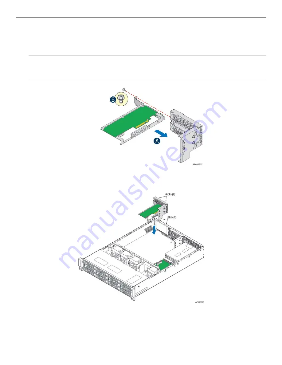
Remove the filler panel from the add-in card slot and remove the fastener screw. 

3.


Insert the SAS Expander till it is fully seated on the riser assembly as shown (see letter “A”). 

Note:

 The SAS Expander should not be installed in the lowest slot of the riser due to the thermal 

reason. 

4.


Secure the SAS Expander with three screws (see letter “B”). 


Figure 27. Installing the SAS Expander 

5.


Align the two hooks on the back edge of the riser assembly with the slots on the back of the chassis, and 

press the riser assembly straight down as shown. 


Figure 28. Installing the Riser Assembly 

6.


Connect all cables back into the SAS Expander connectors. 

Summary of Contents for JBOD2000S3SP

Page 1: ...Intel Storage System JBOD2312S3SP Service Guide A Guide for Technically Qualified Assemblers of Intel identified Subassemblies Products Revision 1 0 Apr 2017 Intel Server Boards and Systems ...

Page 2: ...Intel Storage Server System JBOD2000S3 Service Guide This page is intentionally left blank ...

Page 3: ...Intel Storage Server System JBOD2000S3 Service Guide i Revision History Date Revision Number Modifications Apr 2017 0 6 First preliminary version Apr 2017 1 0 First public version ...

Page 4: ...course of dealing or usage in trade This document contains information on products services and or processes in development All information provided here is subject to change without notice Contact your Intel representative to obtain the latest TPS The products and services described may contain defects or errors known as errata which may cause deviations from published specifications Current char...

Page 5: ... sb cs 010770 htm Consignes de sécurité Lisez attention toutes les consignes de sécurité et les mises en garde indiquées dans ce document avant de suivre toute instruction Consultez Intel Server Boards and Server Chassis Safety Information sur le Intel Server Deployment Toolkit 3 0 CD ou bien rendez vous sur le site http www intel com support motherboards server sb cs 010770 htm Instrucciones de s...

Page 6: ...e chassis add or remove any components Hazardous conditions devices and cables Hazardous electrical conditions may be present on power telephone and communication cables Turn off the server and disconnect the power cord telecommunications systems networks and modems attached to the server before opening it Otherwise personal injury or equipment damage can result Electrostatic discharge ESD and ESD...

Page 7: ...a brief overview of the Intel JBOD 2000S3 System In this chapter you will find a list of the server system features and figures of the system and components to help you identify your system components and their locations Chapter 2 provides instructions on adding and replacing components Use this chapter for step by step instructions and diagrams for installing or replacing components such as the f...

Page 8: ... 5 Back Panel 3 1 6 Hard Disk Drive Carriers 3 1 7 Bezel 4 1 8 Hot Swap SAS SATA Backplane 4 1 8 1 12 x 3 5 inch Hard Drive Backplane 4 1 9 JBOD2312S3SP Interconnection 5 2 Hardware Installations and Upgrades 6 2 1 Before You Begin 6 2 1 1 Tools and Supplies Needed 6 2 1 2 System Reference 6 2 2 Cable Routing 6 2 3 Fan Connections 6 2 4 Removing and Installing the Front Bezel 7 2 4 1 Removing the ...

Page 9: ...he Backplane 16 2 11 1 Replacing the 3 5 Hard Drive Backplane 16 2 12 Installing and Removing the Rack Handles 18 2 12 1 Removing the Rack Handles 18 2 12 2 Installing the Rack Handles 18 2 13 Installing and Removing the Storage Front Panel 19 2 13 1 Installing the Storage Front Panel 19 2 13 2 Removing the Storage Front Panel 19 Appendix A Technical Reference 21 Power Supply Input Voltages 21 Pow...

Page 10: ...3 5 HDD 10 Figure 20 Installing Hard Disk Drive Installing 2 5 HDD 11 Figure 21 Installing Hard Disk Drive Inserting 3 5 HDD Assembly 11 Figure 22 Removing the Power Supply Module 12 Figure 23 Removing the Filler Panel 12 Figure 24 Installing the Power Supply Module 12 Figure 25 Removing the Riser Assembly 13 Figure 26 Removing the SAS Expander 13 Figure 27 Installing the SAS Expander 14 Figure 28...

Page 11: ...Intel Storage Server System JBOD2000S3 Service Guide ix List of Tables Table 1 Power Supply Output Capability 21 Table 2 System Environmental Limits Summary 21 ...

Page 12: ......

Page 13: ...e power supply fan for each installed power supply module Power Supply Options Single AC 460W PSU for JBOD2312S3SP as default configuration second PSU can be suppoted as option Storage Bay Options 12x 3 5 SATA SAS Hot Swap Hard Drive Bays Available Rack Mount Kit Options Tool less rack mount rail kit Intel Product Code AXXPRAIL Value rack mount rail kit Intel Product Code AXXVRAIL Cable Management...

Page 14: ...near the system you can also use the Quick Reference Label provided on the inside of the chassis cover to assist in identifying components Figure 2 Intel JBOD2000S3 System Family Components 1 3 Hot Swap Hard Drive Bay Figure 3 12 x 3 5 Drive JBOD2312S3SP Front View 1 4 Front Panel Label Description A Power Button w Integrated LED B System ID Button w Integrated ...

Page 15: ...ith 3 5 inch hard disk drive carriers See the following table for details Intel JBOD System Supported Hard Drive Type Maximun Hard Drive Number JBOD2312S3SP 3 5 inch 2 5 inch can be supported 12 For instructions on installing hard drives see Installing a Hot swap Hard Disk Drive NOTES Drives can consume up to 17 watts of power each Drives must be specified to run at a maximum ambient temperature o...

Page 16: ...TA backplane serves as an interface between the SAS expander s and the system drives The following diagrams show the location for each connector found on the backplane 1 8 1 12 x 3 5 inch Hard Drive Backplane A SAS SATA Hot swap Connectors Figure 7 12 x 3 5 inch Hard Drive Backplane Components Front View A Mini SAS Connectors B Power Connectors C I2 C Connector Figure 8 12 x 3 5 inch Hard Drive Ba...

Page 17: ...BOD2312S3SP Interconnection The Intel Storage Server System JBOD2312S3SP has a 12x3 5 single port HSBP a primary SAS expander a dual port SAS interface board a PDB a PSU and four fans in its chassis Figure 9 12x3 5 Single port JBOD 2000S3 Interconnection Diagram ...

Page 18: ...driver 2 bit Needle nosed pliers Anti static wrist strap and conductive foam pad recommended 2 1 2 System Reference All references to left right front top and bottom assume the reader is facing the front of the chassis as it would be positioned for normal operation 2 2 Cable Routing When you add or remove components from your JBOD make sure your cables are routed correctly before reinstalling the ...

Page 19: ... right end from the rack handle see letter B Figure 11 Removing the Front Bezel 2 4 2 Installing the Front Bezel NOTE Before installing the bezel you must install the rack handles 1 Lock the right end of the front bezel to the rack handle see letter A 2 Rotate the front bezel clockwise till the left end clicks into place see letter B 3 Lock the bezel if needed Figure 12 Installing the Front Bezel ...

Page 20: ...system cover in place to ensure proper cooling You will need to remove the top cover to add or replace components inside the system Before removing the top cover power down the server and unplug all peripheral devices and the power cable s NOTE A non skid surface or a stop behind the server system may be needed to prevent the server system from sliding on your work surface 1 Observe the safety and...

Page 21: ...chassis and slide forward to engage recessed edge at the front of the cover see letter A 2 Tighten the four screws see letter B Figure 16 Installing the System Cover 2 6 Installing a Hot swap Hard Disk Drive CAUTION If you don t install all drives empty drive bays must be occupied by carriers with plastic drive blank provided to maintain proper system cooling ...

Page 22: ...k Drive Removing 3 5 HDD Interface Bracket 3 Install the hard disk drive using the same four screws as shown Make sure the connector end of the drive matches the backplane connector see letter D Figure 19 Installing Hard Disk Drive Installing 3 5 HDD For installing 2 5 Hard Disk Drive as an option 1 Break off the tab on the HDD interface bracket see letter d1 2 Install the HDD interface bracket fr...

Page 23: ... a redundant system with two power supplies installed If you only have one power supply installed before removing or replacing the power supply you must first take the system out of service turn off all peripheral devices connected to the system turn off the system by pressing the power button and unplug the power cord from the system or wall outlet The power supply can be replaced if it fails To ...

Page 24: ... remove the filler panel see letter B Figure 23 Removing the Filler Panel 2 Do one of the following Insert the power supply module into the power supply cage and push all the way until it clicks into place see letter C Figure 24 Installing the Power Supply Module If no power supply is to be installed install the filler panel into the power supply cage ...

Page 25: ...s from the SAS Expander and remember the connection locations Grasp the riser assembly with both hands and pull up to remove from the system Figure 25 Removing the Riser Assembly 2 Remove the screw from the SAS expander bracket as shown see letter A Pull up the SAS Expander from the riser assembly as shown see letter B Figure 26 Removing the SAS Expander ...

Page 26: ... assembly as shown see letter A Note The SAS Expander should not be installed in the lowest slot of the riser due to the thermal reason 4 Secure the SAS Expander with three screws see letter B Figure 27 Installing the SAS Expander 5 Align the two hooks on the back edge of the riser assembly with the slots on the back of the chassis and press the riser assembly straight down as shown Figure 28 Inst...

Page 27: ...on locations 3 Remove the six screws from the power distribution board see letter A 4 Lift the power distribution board from the JBOD system see letter B Figure 29 Removing the Power Distribution Board 2 9 2 Installing the Power Distribution Board 1 Place the power distribution board into the JBOD system see letter A 2 Secure the power distribution board with six screws see letter B Figure 30 Inst...

Page 28: ...move all hot swap drive carriers regardless of whether or not a drive is installed in the carrier Disconnect all cables from the backplane 2 Remove the six screws to release the hard drive cage see letter A 3 Slide the hard drive cage out of the server chassis The clip will fall out automatically see letter B Figure 32 Removing 3 5 Hard Drive Backplane Remove the Hard Drive Cage 4 Remove the screw...

Page 29: ... Position the backplane in place at the front of the server system see letter A 2 Slide the backplane into the server system guides see letter B 3 Secure the backplane with the screw see letter C Figure 34 Installing 3 5 Hard Drive Backplane Install the Backplane 4 Insert the hard drive cage into the server chassis see letter D 5 Secure the hard drive cage with the six screws see letter E Figure 3...

Page 30: ... Drive Backplane Install the Stiffener and Hard Drives 8 Connect cables to the backplane See Cable Routing 2 12 Installing and Removing the Rack Handles 2 12 1 Removing the Rack Handles Remove the two screws holding the rack handle in place and remove the rack handle from the server system as shown Figure 37 Installing the Rack Handle 2 12 2 Installing the Rack Handles Align the rack handle with t...

Page 31: ...le Routing for more details Figure 39 Installing the Interposer Card 4 Attach the storage front panel to the rack handle on the right side of the server chassis see letter D 5 Fasten the four screws to secure the storage front panel see letter E Figure 40 Installing the Storage Front Panel 2 13 2 Removing the Storage Front Panel 1 Remove the four screws to release the storage front panel see lette...

Page 32: ...orage front panel see letter D 5 Remove the storage front panel from the side wall of the server chassis see letter E Figure 42 Removing the Interposer Card 6 Connect the front panel control cable from the motherboard to the standard front control panel if needed See Cable Routing for more details ...

Page 33: ...ing and non operating environmental limits Table 2 System Environmental Limits Summary Parameter Limits Operating Temperature 10 C to 35 C with the maximum rate of change not to exceed 10 C per hour Non Operating Temperature 40 C to 70 C Non Operating Humidity 90 non condensing at 35 C Acoustic noise Sound power 7 0 BA in operating condition at typical office ambient temperature 23 2 C Shock opera...

Page 34: ...ce Guide 22 Appendix B Regulatory and Compliance Information Please refer to the Server Products Regulatory and Safety document for the product regulatory compliance reference The document can be downloaded from http www intel com support server ...

Page 35: ...ds chassis support matrix and operating systems Server and chassis accessory parts list for ordering upgrades or spare parts A searchable knowledgebase to search for product information throughout the support site 2 If you are still unable to obtain a solution to your issue send an email to Intel s technical support center using the online form available at http www intel com support feedback htm ...

Page 36: ...Intel Storage Server System JBOD2000S3 Service Guide 24 Appendix D Warranty Information To obtain warranty information visit the following Intel web site http www intel com support warranty ...

Reviews: