


Intel® Thermal/Mechanical Reference Design Information
R
Thermal/Mechanical Design Guide
43
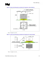
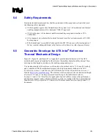
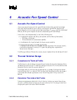
Figure 9. Shock Acceleration Curve
0
10
20
30
40
50
60
0
2
4
6
8
10
12
Time (m illiseconds)
A
c
c
e
l
e
r
a
t
i
o
n
(g)
5.2.1.2.1
Recommended Test Sequence
Each test sequence should start with components (i.e., motherboard, heatsink assembly, etc.) that
have not been previously submitted to any reliability testing.
The test sequence should always start with a visual inspection after assembly, and
BIOS/Processor/Memory test (refer to Section 5.2.3).
Prior to the mechanical shock and vibration stress test, the units under test should be
preconditioned for 72 hours at 45 ºC. The purpose is to account for load relaxation during burn-in
stage.
The stress test should be followed by a visual inspection and then BIOS/Processor/Memory test.
5.2.1.2.2
Post-Test Pass Criteria
The post-test pass criteria are:
1.
No significant physical damage to the heatsink attach mechanism (including such items as
clip and motherboard fasteners).
2.
Heatsink must remain attached to the motherboard.
3.
Heatsink remains seated and its bottom remains mated flatly against IHS surface. No visible
gap between the heatsink base and processor IHS. No visible tilt of the heatsink with respect
to its attach mechanism.
4.
No signs of physical damage on motherboard surface due to impact of heatsink or heatsink
attach mechanism.
5.
No visible physical damage to the processor package.
6.
Successful BIOS/Processor/memory post-test of samples.
7.
Thermal compliance testing to demonstrate that the case temperature specification can be
met.
Summary of Contents for 640 - Pentium 4 640 3.2GHz 800MHz 2MB Socket 775 CPU
Page 14: ...Introduction R 14 Thermal Mechanical Design Guide ...
Page 38: ...Thermal Management Logic and Thermal Monitor Feature R 38 Thermal Mechanical Design Guide ...
Page 52: ...Intel Thermal Mechanical Reference Design Information R 52 Thermal Mechanical Design Guide ...
Page 60: ...Acoustic Fan Speed Control R 60 Thermal Mechanical Design Guide ...
Page 72: ...Heatsink Clip Load Metrology R 72 Thermal Mechanical Design Guide ...
Page 99: ...Mechanical Drawings R Thermal Mechanical Design Guide 99 Figure 50 Reference Fastener Sheet 1 ...
Page 103: ...Mechanical Drawings R Thermal Mechanical Design Guide 103 Figure 54 Clip Heatsink Assembly ...


