10
4.Installation
Maximum alignment deviations:
Outside diameter of
the coupling [mm]
Va
min
[mm]
Va
max
[mm]
Va
max
- Va
min
[mm]
Vr.
[mm]
70 - 80
2
4
0,13
0,13
81 - 95
2
4
0,15
0,15
96 - 110
2
4
0,18
0,18
111 - 130
2
4
0,21
0,21
131 - 140
2
4
0,24
0,24
141 - 160
2
6
0,27
0,27
161 - 180
2
6
0,3
0,3
181 - 200
2
6
0,34
0,34
201 - 225
2
6
0,38
0,38
4.5.
PIPES
•
In general, suction and delivery pipes should be fitted in straight stretches, with the minimum amount of elbows and
accessories, in order to reduce, as far as possible, any head loss that might be produced by friction.
•
Make sure that the pump ports are well aligned with respect to the piping and that they are similar in diameter to that of
the pipe connections.
•
Position the pump as near as possible to the suction tank, and whenever possible below the level of the liquid or even
lower with respect to the tank in order for the static suction head to be at its maximum.
•
Place brackets for the piping as near as possible to the suction and delivery ports of the pump.
4.5.1.
Shut-off valves
The pump can be isolated for the purpose of carrying out maintenance work. To this end, shut-off valves should be fitted at the
pump’s suction and delivery connections.
These valves must ALWAYS be open whenever the pump is operating.
4.5.2.
Self-priming process
In general terms --if the self-priming process is followed-- the pump ought to contain sufficient liquid to fill the internal
recesses and the void spaces thus enabling the pump to create a pressure difference.
However, if low viscosity fluids are to be pumped, a foot valve of the same or greater diameter as that of the suction pipe
should be installed; alternatively, the pump can be installed with a "U" shaped piping.
The use of a foot valve is not recommended for pumping viscous liquids.
•
In order to eliminate air and gases from the suction pipe, the counter-
pressure on the discharge pipe should be reduced. When the self-
priming process is used, the pump's start-up should be done by
opening and emptying the discharge pipe which allows the air and
gases to escape at a low counter-pressure.
•
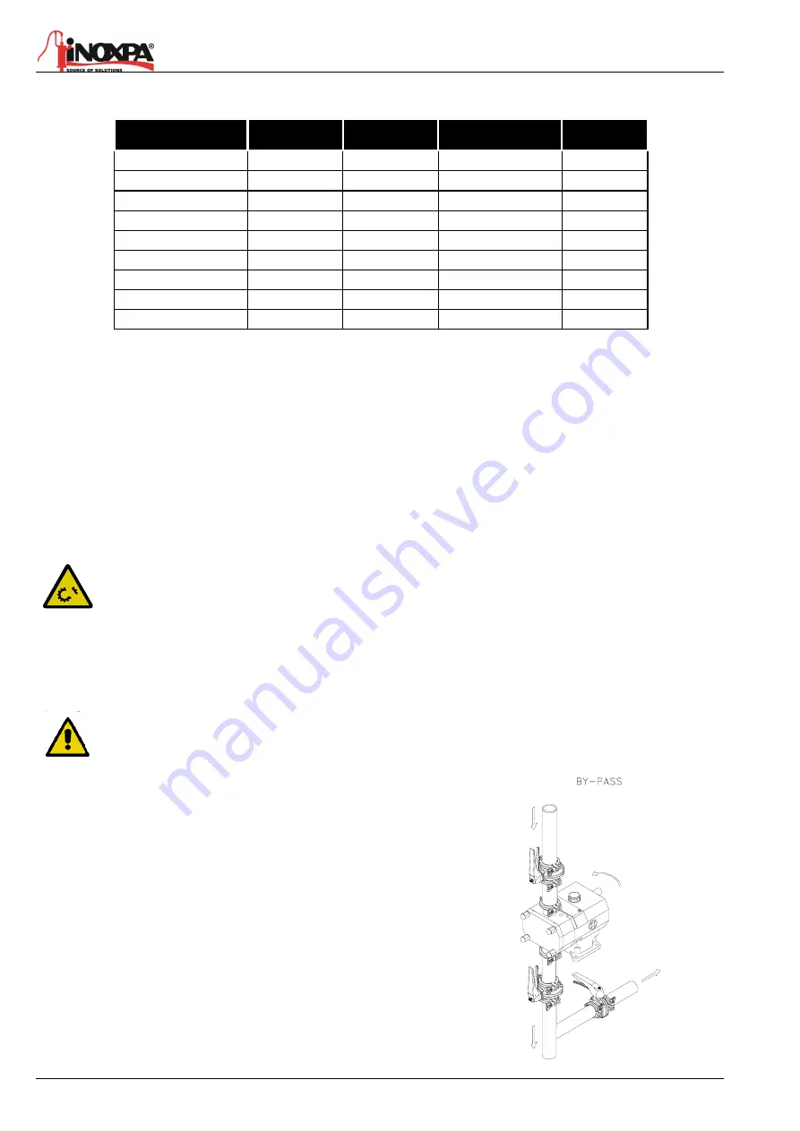
Another possibility involves long pipes or when a check valve is
installed in the discharge pipe; it is also possible to install a by-pass
with a shut-off valve on the discharge side of the pump. This valve
shall be opened in the case of priming and will allow air and gases to
escape at a minimum counter-pressure.
•
The by-pass should not lead back to the intake orifice but to the
supply tank instead.
Summary of Contents for HLR
Page 2: ......
Page 3: ......
Page 35: ...34 8 Technical Specifications A 2021 11 8 5 HLR 0 8 5 1 Exploded view...
Page 37: ...36 8 Technical Specifications A 2021 11 8 6 HLR 1 8 6 1 Exploded view...
Page 39: ...38 8 Technical Specifications A 2021 11 8 7 HLR 2 8 7 1 Exploded view...
Page 41: ...40 8 Technical Specifications A 2021 11 8 8 HLR 3 8 8 1 Exploded view...
Page 43: ...42 8 Technical Specifications A 2021 11 8 9 HLR 4 8 9 1 Exploded view...


