


10.24.16 06755A_v6 © Inovonics, 2016 - www.inovonics.com
EN1244/EN1244-60/EN1244A/EN1244Z
Wireless Smoke Detector
Installation Instructions
1 Overview
The wireless smoke detector features an onboard sounder, a smoke
sensor, an LED indicator and local test capability to allow the user total
visibility of its functionality. It is self-monitoring, alerting the user when
sensor maintenance is needed or batteries are low, and automatically
supervising the radio link.
The EN1244 and EN1244-60 wireless smoke detector have been designed
for operation in the United States; the EN1244A wireless smoke detector
has been designed for operation in Australia; and the EN1244Z wireless
smoke detector has been designed for operation in New Zealand.
The EN1244 wireless smoke detector is intended for open area protection
and for connection to a compatible power supply or control unit for
operation as part of a household fire alarm system (UL985).
Note:
For UL 2560 installations, refer to the
EN6080 Area Control
Gateway Installation Instructions
.
1.1 Maximum Number of Repeaters for a UL 2560
Installation
To achieve the 99.99% alarm message reliability required for UL 2560
compliance, system installations must operate within the following limits for
end device and repeater counts.
1.2
Inovonics Contact Information
If you have any problems with this procedure, contact Inovonics technical
services:
• E-mail: [email protected].
• Phone: (800) 782-2709; (303) 939-9336.
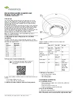
1.3 Wireless Smoke Detector External Components
Figure 1
Wireless smoke detector external components
Device Indicators
1.4 What’s In The Carton
• One 3V-Lithium battery, installed.
• Two drywall anchors.
• Two mounting screws.
2 Installation and Startup
2.1 Installation Notes
• These products are designed to be maintained by professional
security technicians.
• Products are tested for indoor use.
• All products should be manually tested weekly.
2.2 Activate the Battery
1.
Remove the orange dust cover.
Note:
If the detector cover is loose it can detach while removing the dust
cover. If the detector cover is removed with the orange dust cover, place
End
Devices
Maximum
Repeaters
150
397
250
386
350
375
500
360
1000
313
2000
238
3000
184
For product and installation videos visit us at
www.inovonics.com/videos or use the QR
code below.
Green LED
Red LED
Sounder
Power up
Both LEDs
blink every 5
seconds
Both LEDs
blink every
5 seconds
Off
Normal
(standby)
Blinks every
10 seconds
Off
Off
Sensitivity out of
range
Off
Blinks
every five
seconds
Off
Smoke alarm
Off
Lit
Temporal
pattern
Low battery
Off
Blinks
every 45
seconds
Chirps every
45 seconds
beginning
seven days
after the LED
begins
blinking
Test
button
Green
LED
Red
LED