background image

 Opening the Scanner  

User Manual H12 / SCAMAX® 8x1 - Version 2019.12

Page 103 of 136

6.2. 

Opening/Closing the Output Hopper(s)

Since the procedure differs between the variant with two Output Hoppers and that equipped with 
one Output Hopper, we explain the opening/closing below

...

6.2.1. 

... with One Output Hopper

The Unlocking of the Output Hopper is located on the 

right and left of the paper ejection. If a HighSpeed Sta-

cker Arm (

see chapter


5.7.2.

) is used, this is right in bet-

ween. To open, one of the Unlocking buttons is pushed 

up and the top part of the Output Hopper folded back-

wards. To close, the top part is guided to the front and 

engaged with light pressure from above the lock.

6.2.2. 

... with Two Output Hoppers

If the scanner is equipped with a 2nd Output Hopper, opening and closing of the 2nd Output Hopper 

is identical to the description in the previous chapter. Since the 2nd Output Hopper is placed on top 

of the Output Hopper and this is also folded up when opening the Output Hopper, the procedure for 

opening/closing the Output Hopper is different in this case.

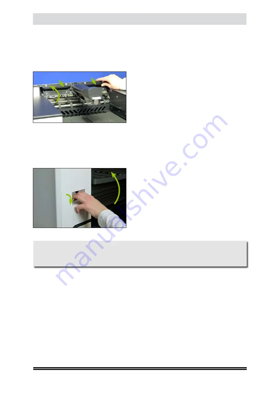
Now the Unlocking of the Output Hopper is located in a 

grip depression that is integrated in the front left of the 

housing of the 2nd Output Hopper. To open, the Unlo-

cking latch is pulled forward and the top of the Output 

Hopper, along with the attached 2nd Output Hopper is 

opened until resistance is felt, from point this part slides 

independently to the rearmost position. To close, guide 

the open part forward again until the lock snaps in place.

Warning

Before closing the Output Hopper with an attached 2nd Output Hopper, it is essential to ensure 

that within the area of the 2nd Output Hopper, on which the Output Hopper 

(

see chapter 

1.2.2.3.

)

rests, no body parts or objects linger in order to avoid injury or damage.

Summary of Contents for SCAMAX H12

Page 1: ...User Manual SCAMAX Document Scanner Type H12 Version 2019 12 InoTec GmbH Biedrichstrasse 11 61200 Woelfersheim Tel 49 0 6036 9708 0 Fax 49 0 6036 9708 15 eMail info inotec eu http www inotec eu...

Page 2: ...Spot Crush Jam 2 14 1 2 2 5 Danger Spot Crush Jam 3 14 1 2 2 6 Danger Spot Electrical Voltage 14 2 General description 15 2 1 SCAMAX upgrade concept 801 811 821 16 2 2 Extensions options 16 2 2 1 Dual...

Page 3: ...f Drivers 25 3 6 1 USB Device Driver 25 3 6 2 TWAIN Driver 25 3 6 3 ISIS compatible Driver MS61 26 4 Capacitive Touchscreen 27 4 1 Division of the Display Surface 27 4 1 1 Status 27 4 1 2 User 27 4 1...

Page 4: ...6 2 1 4 Add Remove Borders 43 4 6 2 1 5 Resize Image 44 4 6 2 2 Color Dropout 44 4 6 2 2 1 Separate Channel 44 4 6 2 2 2 Dropout Setting 1 3 45 4 6 2 2 3 Fill Color 46 4 6 2 2 4 Dropout at 46 4 6 2 3...

Page 5: ...ction at Detection 63 4 6 4 1 4 Show DF Images 63 4 6 4 1 5 Continue after Delete 63 4 6 4 1 6 Sensor Configuration 64 4 6 4 2 Control Settings 64 4 6 4 2 1 Scan Speed 65 4 6 4 2 2 Use High Speed Stac...

Page 6: ...nt Text 75 4 6 6 2 4 Font 76 4 6 6 2 5 Background 76 4 6 6 2 6 Positioning 76 4 6 7 Interfacing 76 4 6 7 1 Enable Length Control 77 4 6 7 2 Error Handling on Scanner 77 4 6 7 3 Wait for Paper 77 4 6 8...

Page 7: ...4 Input Hopper 90 5 4 1 Input Plate 90 5 4 2 Setting Options Paper Input 90 5 4 3 Using the Single Input Hopper 91 5 4 4 Using the Dual Input Hopper 92 5 5 Scan Plane 93 5 5 1 Scan Background 93 5 5 2...

Page 8: ...2 4 Replacing the Separation Roller Friction Linings 109 7 3 Cleaning Maintenance of the Scan Plane 109 7 3 1 Cleaning the Ultra Sonic Sensors 110 7 3 2 Cleaning the Scan Areas 110 7 3 3 Vacuum Cleani...

Page 9: ...206 207 121 9 2 6 2nd Output Tray Full Error 208 209 121 9 2 7 Paper Jam at Paper Input Error 210 122 9 2 8 Paper Jam at Scan Area Error 211 237 238 239 240 122 9 2 9 Paper Jam at Rear Output Area Er...

Page 10: ...0 128 9 2 36 Linak Error Detected Error 252 128 9 2 37 Linak Uncalibrated Error 253 128 9 2 38 Double Feed at Paper Input Detected Error 254 128 9 2 39 Barcode Check Digit Wrong Error 255 129 9 2 40 B...

Page 11: ...experts Under normal conditions the removing of housings isn t necessary Risk due to moving parts Keep fingers and other body parts away 1 2 Specific Danger Spots While running moving or opening and c...

Page 12: ...ring the lateral movement of the Dual Input Hopper in case of a refe rence move or an Input Tray switching its center bridge moving along the housing edges The distance between the center bridge and t...

Page 13: ...r Assembly and the front Transport Rollers of the Paper Output in the Output Hoppers are pointed as danger spots While the Paper Transport is running it is not allowed to grab into the moving areas an...

Page 14: ...1 2 2 5 Danger Spot Crush Jam 3 Also this warning icon is related to the Height Adjustment of the scanner and indicates to the possible risk of crush or jam the body while lower the scanner Because of...

Page 15: ...documents in batch mode Optionally the device can also be equipped with a Dual Input Hopper This doubles the feeder capacity and enables continuous processing The integrated and controllable ultrason...

Page 16: ...t Input Trays with a capacity of 1 000 sheets each which are alternately executed In order for the scan operator to have the option to fill the empty Input Tray with documents without having to interr...

Page 17: ...tion to gradual increase the straight through paper path by more than 100 For more information please refer to chapter 5 7 6 1 2 2 6 Extension kits for over sized documents If you need to process docu...

Page 18: ...Section green area Thelocationofthemaincomponentsandfunctiongroupsandtheir names are shown in the figures in the following chapters 2 3 1 Front Views As the devices of the H12 type can be extended by...

Page 19: ...3 2 Rear View Subsequently the rear view of a model of the Full Expansion Stage 2nd Out put Hopper Output Hopper Output Tray 2nd Out put Tray Shelf Left Touchscreen Capacitive Dual Input Hopper Input...

Page 20: ...Plane 2 3 4 View Imprinter The images that follow clarify the positions of the two standard imprinters available Roller Assembly Separation Roller Document In put Detection PreScan Print Area Front Sc...

Page 21: ...050 Friction Lining Green with Riffles 2 pcs e 007 3053 Friction Lining Red 2 pcs e 007 3055 Friction Lining Red with Riffles 2 pcs e 007 3057 Friction Lining White for Separation Roller 2 pcs e 007 3...

Page 22: ...necessary to partly dismantle it before moving the scanner to a new location Therefore in most cases relocating the unit will require assistance by an authorized expert Even if the scanner can be mov...

Page 23: ...your scanning PC for the first time a matching USB device driver must be available there Driver installation will be covered in detail in chapter 3 6 3 4 3 USB Ports for Input Devices or Data Storage...

Page 24: ...can transformed from the energy saving mode to the active mode by pressing the green button Start Pause which is centrally located on the Dual Input Hopper or on the right on the Single Input Hopper...

Page 25: ...required for interfacing to the scanner The installer file is labelled TwainSetupScamaxUSB3 exe and may be found on the USB flash drive shipped with the scanner Alternatively the installer may be dow...

Page 26: ...er MS61 Another special driver for all scan software depending on the ISIS communication protocol is also supplied The installer file is labelled ISISSetupScamaxUSB3 exe and may also be found on the U...

Page 27: ...whether the scanner is active in operational condition green or a warning yellow or error red In addition a unique icon and the current status or the warning or error mes sage is displayed In the case...

Page 28: ...i e within the masks of a menu level or via keys control one level forward or backward Only using the navigation bar does one for example from a mask of the menu Level 4 directly reach the drop down m...

Page 29: ...o Unlike in this round field which is also displayed to the left of the menu bar This is a option field which is used to select the desired option from a group of possibilities There are at least two...

Page 30: ...xt The uppermost key combination shown to the left will copy highlighted text whereas the key combination in the middle will cut remove highlighted text The lower most key combination will insert copi...

Page 31: ...ion of any patch code alternatively the absence of any patch codes Every sheet scanned or as a subset thereof every sheet transfer red Reaching the trigger value of one of the four counters Every barc...

Page 32: ...op three rows of each column are used for displaying Stream Information The images of different color depths are designated this way The icon to the right of the line featuring the particular color de...

Page 33: ...de the four available counters of the system How these counters are named or used depends on the respective configuration see chapter 4 6 5 1 4 3 1 5 Button Bar Whenever the scanner is ready and provi...

Page 34: ...ction Tapping the EndEdit button will end the modification mode Any new key assignments will remain in effect until a different scanning profile is selected or until the scanning software is stopped o...

Page 35: ...user see chapter 4 1 2 and comprises the two fields shown to the left Tapping the Password field will launch a keypad see chap ter 4 2 1 which you should use to enter a new password Tapping the User...

Page 36: ...ay be edited with any of the five buttons shown along the bottom edge of the display area The create button will add a new fresh job definition to the list simply enter the desired name and click OK I...

Page 37: ...existing Scan Profiles see chap ter 4 6 in the display area are listed and can be enabled by selecti on for use in the current job The field Default Profile at the end of the mask allows you to select...

Page 38: ...019 12 Page 38 of 136 4 5 4 Index File If index data should be storedtogetherwiththe generated image files this can be defined via the menu item Index File Since these settings relate to the internal...

Page 39: ...ol bar Whilst the create key generates a new profile based on default values after entering a profile name into a keypad and confirming with OK a copy of the previously selected profile is created wit...

Page 40: ...e of these function keys whenever this scan profile has been selected This setting does not apply to the Quick Access Buttons described below 4 6 1 3 Quick Access Buttons Use these four assignment fie...

Page 41: ...fore scanning a document which would otherwise trigger a double feed detection error makes it pass without interruption This appro ach only makes sense if Error has been selected as the Reaction at De...

Page 42: ...file settings that defines the creation of digital images can be selected via six subme nus Selecting one of the menu items bran ches directly to the as sociated setting masks which are explained in d...

Page 43: ...ses and provides the brightening of darker color zones by its reduction 4 6 2 1 3 White Background Checking White Background will inform the profile of the fact that the Scan Background has been switc...

Page 44: ...mageislargerthanthewidthand orheightspecifiedhere 4 6 2 2 Color Dropout This screen covers all functions available for color removal and also specifies which image types they are applied to Two main m...

Page 45: ...te the color selec tion area just below Tapping this field will open the color picker dialog seechapter4 2 2 which you can use to precisely set a Dropout Color The slide controls in this section will...

Page 46: ...evels will be not be taken into account With the exception of User Color all other Dropout Colors are preset to a Brightness value of 128 and a Saturation value of 255 Therefore the respective default...

Page 47: ...side it is called simplex scan If more than one image type is en abled on one side it is called dual or multi stream With the fields on the right side one comes to the respective settings Checking Str...

Page 48: ...ompressiontoswitchbet ween JPEG compressed default and uncompres sed color image output When selecting compres sed transmission you may also specify the desired JPEG Quality The default value 75 will...

Page 49: ...com pression Binarization All controls on this page are required to fully parameterize the dynamic binarization fun ction However the three settings for Brightness Contrast and Outlining having the b...

Page 50: ...is 0 255 with the setting s effect reversing at midpoint For Contrast settings from 0 to 128 the image background will be in creasingly attenuated in relation to the image foreground Beyond midpoint...

Page 51: ...ogo s shapes and lettering can still be fully recognized After increasing the Outlining level to 100 the shape on the left side of the logo is no longer recognizable and the lower logo area has been s...

Page 52: ...n of Stream Control may be performed through the following settings screens Checking the option at the top of the General screen will either activate Copyto Back front side or Same as Front back side...

Page 53: ...All it will need to do instead is to apply blank page detection and remove any small white images On the Events screen you can define various me thods for event driven switching of image type Three d...

Page 54: ...nd whereas AnyColorDetected responds to color information found in the image foreground LikelyUnsafeBinarization is based on a threshold value indicating that too much detail information would be lost...

Page 55: ...tings pages The General settings page contains just one control The Copy to Back option visible when editing front sidesettings and the Same as Front option visible when editing back side settings wil...

Page 56: ...at define the paper in put and the image ori entation can be selec ted by five sub menus Selecting one of the menu items branches directly to the associa ted setting masks which are explained in detai...

Page 57: ...levels The default value Normal refers to the state without elevation The step should be adapted to the thickness of existing Scan material because just as the material from a certain thickness is to...

Page 58: ...t and lowered afterwards 4 6 3 2 2 Separation Via this option the Separation Roller can be de activated in the input area see chapter 5 3 which possibly separates the documents adhering to one another...

Page 59: ...ted into output tray 2 This is accompanied with the special handling feature described in the previous chapter If both settings are unavailable grayed out setting Switch Out1 Out2 at described in the...

Page 60: ...been specified for PaperInputOrientation above this will determine the amount of rotation applied to output images 4 6 3 4 3 Additional Back Orientation If images on rear sides need to be differently...

Page 61: ...lly dark documents lowering the threshold value and when using Gamma Correction see chapter 4 6 2 1 2 increasing the threshold value will help very often 4 6 3 5 2 Deskew Fill Color Although the Deske...

Page 62: ...ems 4 6 4 1 Double Feed Detection Use this screen to con figure Double Feed De tection The following discussion of configu ration items includes various combinations of activated and deac tivated sett...

Page 63: ...ther Delete or Transfer the images which caused the double feed condition Ignore prevents a response to the Double Feed Detection The scanning process continues In spite of this the resulting Double F...

Page 64: ...ference zone along the direction of paper travel which is utilized on the Scope screen For each of the three ultrasonic sensors the three fields on the Scope screen specify if detection will be perfor...

Page 65: ...ection range of the Stack Height Sensor Near default will detect up to distances of about 80 mm whereas Far is intended for special applications and will extend the detection range to as much as 160 m...

Page 66: ...ion from optimizing document gaps This might be advisable if there are increased paper jams in the scan ner s input section see chapter 9 2 7 when processing heavy duty documents and might also help w...

Page 67: ...ntirely 4 6 4 3 2 Read Area These three fields specify the detection area used by the cameras when searching for patch codes The upper two values limit the detection area horizontally and are both ent...

Page 68: ...canning will be interrupted Verified Detection at Input will reduce the risk of invalid imprints on any documents causing erroneous patch code detection 4 6 4 3 6 Delete Patch Code Sheets Checking thi...

Page 69: ...r message see chapter 9 2 40 and scanning will be interrupted 4 6 4 4 3 Threshold As is the case with patch code detection see chapter4 6 4 3 3 you may adjust Threshold for detecting bar codes with le...

Page 70: ...erent scanning profile Selecti on is through a dynamic drop down list which will display all profiles available on this scanner The default entry is OwnProfile profilename and refers to the currently...

Page 71: ...Trigger Value for this counter Whenever the counter reaches this value it will produce a trigger event Such trigger events will appear in the event list see chapter 4 2 3 as Counter X triggered to us...

Page 72: ...ent or manually started by one of the Quick Access Buttons Between the entry field Print Text and the keyboard an area will appear where a list of all available print va riables and print attributes c...

Page 73: ...f type Code 128 For more information about these algorithms and their prerequisites please refer to respective expert literature Note CD4_8 refers to a proprietary algorithm which will not be elaborat...

Page 74: ...rd height and one line at triple height One line at quadruple height Barcode Print HD The optional HD Imprinter is capable of reproducing three different bar code types at three different widths When...

Page 75: ...n accordingly This happens whenever you first select OtherSide ImprinterFront or ImprinterBack which effectively copies the configuration from the other side of the document or from one of the imprint...

Page 76: ...are created 4 6 6 2 5 Background If you want to avoid image data interfering with the contents of the digital image stamp you may add a defined background using these two fields Configuration is iden...

Page 77: ...when starting a new scan If set to 0 the scan ner will assume that documents have already been placed in the active input tray before scan start With a setting of 10 default however the scanner will w...

Page 78: ...ove Counter 1 is supposed to be reset either as soon as its trigger value is reached or whenever Patch 1 is detected Firstly open the rules overview screen by tapping Edit Rules Next for the sake of s...

Page 79: ...actions are also available for Tray 2 and the rear output tray with rear corresponding to Switch front rear None of these actions require reference items The actions shown to the left refer to contro...

Page 80: ...rule Such conditions are initially defined as indi vidual Simple Rules but without an Action specified If a Simple Rule with an Action is inadvertently added to a Complex Rule this will result in a c...

Page 81: ...ith another condition Inordertoillustratethisprinciple wellexpandtheexamplefromabovewithanadditionalrequirement Images for all documents with a length of 150 mm also need to be discarded if a Patch T...

Page 82: ...fault user scan is also shown in gray because it may not be modified at all by definition Tapping create in the button bar at the bottom of the screen will add a new user account The keypad will open...

Page 83: ...bration Tapping this button will initiate a white balance calibration of the scanner s internal cameras Again before beginning the unit s scan area must be thoroughly cleaned If a Gain Calibration see...

Page 84: ...ionCode at the bottom of the screen may be used to add further options To do so first enter an option code using the keypad then tap button Apply If the option code is invalid you will receive the err...

Page 85: ...enever a scanner error occurs or if the Pause button is pressed The exact behavior depends on the choice made in the profile setting of the same name seechapter4 6 4 2 4 The output tray will be lowere...

Page 86: ...sh drive containing a j p export ino file needs to be inserted into one of the available USB2 ports If this file is missing or corrupted or if the configuration profiles contained in the file are inco...

Page 87: ...ted into one of the available USB2 ports During this process a new folder is created on the flash drive The folder name is composed out of a combination of scanner model serial number date and time Th...

Page 88: ...must be pushed to the edge pointing towards the document feeder Documents that do not lie at the edge necessarily produce a Double Feed see chapter 9 2 14 If the centered input is used seechapter 5 4...

Page 89: ...and a dial slightly above the knob This dial serves as an indicator for contact pressure and features a scale with several thin lines and one bold line Each line corresponds to one revolution of the...

Page 90: ...e input plate align with the notches in the mounting base Next push the input plate to the front until the two brackets on the underside of the input plate move under and engage with the front section...

Page 91: ...eased inclinationwillensureoptimalpapertransportforlonger documents For batch processing the InputTray is filled with a stack of prepared documents see chapter 5 1 It should be ensured that the docume...

Page 92: ...y filled with the next paper stack If the currently processed Input Tray is empty the Dual Input Hopper moves to the left or right to position the filled InputTray under the feeder system while the em...

Page 93: ...he green dials which are located at both sides of the Scan Background the Paper Passage Setting i e the distance between the glass guides of the Scan Module and the Scan Background can be varied in th...

Page 94: ...tioning paper input off center it may happen that some documents are dragged along but not over one of the roller sets causing creased or folded edges In order to fix this it is possible to move indiv...

Page 95: ...stheInputHopper seechapter 5 4 2 every Output Hopper has lateral Paper Guides that can be manually adjusted to the width of the documents to be processed In contrast to Input Hoppers these two Paper G...

Page 96: ...the following image series the HighSpeed Stacker Arm is first folded upwards to change the stop length at the same time the OutputTray is lowered somewhat Now the head of the arm may be pushed back t...

Page 97: ...tegrated magnet holder is simply attached to the counterpart on the head of the HighSpeed Stacker Arm 5 7 3 HighSpeed Open Output Mode In relation to the two output systems and their different way of...

Page 98: ...d documents are generally ejected into the corresponding Output Tray which are not sorted out by project dependent settings into the Rear Output Tray If the HighSpeed Output Mode is used seechapter 5...

Page 99: ...ted to a document length of about 30 cm The ejected documents can be easily removed by the intervention on its back side Primarily this should give the possibility to sort out individual do cuments fr...

Page 100: ...levation see chapter 4 6 3 1 2 enabled the complete top scanner housing will be raised accordingly through motorized action Depending on the elevation level specified this may take up to several secon...

Page 101: ...ware the Scan process can be started and stop ped using the functions available there The scanner adopt the command of the scan software and switches to the appropriate mode Ideally this also works in...

Page 102: ...area in case of an feeder error or paper jam Opening the Scan Plane to the first step is also possible using the Open button that appears in case of some errors see chapter 9 2 18 ff and as a fuction...

Page 103: ...ng of the 2nd Output Hopper is identical to the description in the previous chapter Since the 2nd Output Hopper is placed on top of the Output Hopper and this is also folded up when opening the Output...

Page 104: ...scanner is equipped with a 2nd Output Hopper a short transport path is located between it and the Output Hopper which in the case of a paper jam in this area can be reached only by folding the Interme...

Page 105: ...is covered by the Base Cover These must be removed first previous chapter the Pressure Unit is to be taken out in case of a fault or for cleaning The Rear Output Pressure Unit is fixed laterally with...

Page 106: ...th a Cleaning Accessory Set It is part of the Accessory Set H12 see chapter 3 1 and contains the most important utensils necessary for the maintenance of the scanner If you want to order indi vidual p...

Page 107: ...ung out to the right To remove the Input Rollers the Assembly is taken in handwiththerollersupwardsandthetwolockinghooks forward Now press both hooks in succession forward while gently pressed from be...

Page 108: ...sage see chapter 9 1 3 9 1 14 will be shown on the scanner s display 7 2 2 Replacing the Feeder Roller Friction Linings If occurring feeder error see chapter 9 2 7 due to wear and can no longer be fix...

Page 109: ...much harder material used for the linings of the Separation Roller as for the Feeder Roller Friction Linings see chapter 7 2 2 It is necessary to press the linings with your thumb around outwards ove...

Page 110: ...for Optics 7 3 3 Vacuum Cleaning Below the Scan Plane As mentioned at the beginning of the main chapter accrued dust and other impurities should be sucked from the scanner at intervals basis vacuum cl...

Page 111: ...ngs located opposite the optical sensors The Paper Guide Springs are kept in place by means of a locking device that engages in the hole on the front side of the spring and lateral webs on the rear si...

Page 112: ...uments with the Imprinter Front prior to scanning This also means that these printed information can also be seen on the images of the scanned documents If not desired the Imprinter Back next section...

Page 113: ...ge To remove and install the ink cartridge of an Imprinter first the access to the respective holder has to be established see chapter 8 1 8 2 In case of using the default imprinter types hold the ink...

Page 114: ...11 ml ink quantity according to the manufacturer approximately 3 million characters can be printed in a sing le line height at a resolution of 300 dpi Increasing the resolution to 600 dpi however redu...

Page 115: ...ale s in the Input Hopper s with the script ABC in order that if necessary to adjust the document path to the selected printing position with the present Paper Guides see chapter 5 4 2 5 7 1 Because t...

Page 116: ...redstatusarea Duringscan ning an error message is always accompanied by the interruption of the scanning process In addition to the error number the short description of the error and its correction t...

Page 117: ...tially only in the status area meaning that the concerned HighSpeed Stacker Arm is not in the position required to operate the current out put mode seechapter 5 7 3 To eliminate the respective warning...

Page 118: ...113 These warnings appear initially only in the status area and point out that the Cover Output Hopper or 2nd Output Hopper is not properly closed To eliminate the respective warning it must be check...

Page 119: ...er output should be che cked as soon as this warning occurs and a new cartridge inserted if necessary 9 1 14 Roller Assembly Not Installed Warning 130 This warning is initially only displayed in the s...

Page 120: ...e and the remainder of the documents can now be ejected via the adjacent Transport key This button too only activates paper transport for as long as the key is pressed This way documents stuck in the...

Page 121: ...sition Error 204 205 These errors are displayed when a scan process was started and the corresponding HighSpeed Stacker Arm was not in the position to operate the current output mode see chapter 5 7 3...

Page 122: ...can material can be removed from the Scan Plane Under certain circumstan ces also the Rear Output Pressure Unit must be removed see chapter 6 6 After closing the Scan Plane the scan process can be res...

Page 123: ...riggered To eliminate the respective error the documents in the tray in question must be well arranged Before anew Scanstart proceed according to General Paper Jam Handling see chapter 9 2 9 2 13 Pape...

Page 124: ...that a calibration procedure see chapter 4 7 2 initiated before could not be carried out properly For further steps the enforcing adminis trator or service engineer is to be notified 9 2 18 Paper Insi...

Page 125: ...ndling see chapter 9 2 If the error is not eliminated that way it may also indicate that scraps of paper staples or the like are stuck in the respective area Please open the corresponding Output Hoppe...

Page 126: ...pter 4 6 3 1 1 Depending on the Orientation setting see chapter 4 6 3 4 this may also be the width of the format To fix the error before anew Scanstart proceed according to General Paper Jam Handling...

Page 127: ...rror occurs again please contact your administrator to have the scanner recalibrated 9 2 31 Export Media Not Found Error 246 251 270 This error is displayed if a USB flash drive cannot be found or wri...

Page 128: ...e scanner see chapter 5 2 Please check that the scanner is not overloaded with documents in the input and or output trays and that there are no obstacles in the path of travel during heightadjustment...

Page 129: ...to General Paper Jam Handling see chapter 9 2 and make sure to also check the barcode on the offending document 9 2 41 Double Feed Detected Too Late Error 257 This message is displayed if the detectio...

Page 130: ...ome of the errors may contain function keys that allow General Paper Jam Handling seechapter 9 2 to be per formed In all other cases the scanner will have to be restarted If the state cannot be elimin...

Page 131: ...not have enough contrast at B W images Remedy 2 Use of color filter features is recommended Cause 3 LED Illumination Unit is soiled or partially damaged so that a uniform illumination is no longer pr...

Page 132: ...on Automatic Color Detection and or Event Control e g Patch Code Blank Page Detection Content based dynamic procedure with 2 definable impact areas Paper Processing Handling Working Height Motor driv...

Page 133: ...ma tion and freely definable Interfaces Operation Via Capacitive 9 MultiTouch Communication Panel MTCP with integrated user management Supported OS Windows 7 8 32 64 Bit Windows 10 64 Bit Driver TWAIN...

Page 134: ...simplex sheets per minute 215 220 78 Format letter landscape duplex pages per minute 430 440 156 Scan Performance SCAMAX 821 at 200 300 dpi 400 600 dpi Format A4 portrait simplex sheets per minute 22...

Page 135: ...13 Cover Output Hopper Top Opened 9 1 9 114 Changing Straight Through Paper Path 9 1 10 125 Test Scan Mode is Active 9 1 11 127 Rear Output Active 9 1 12 128 Imprinter Front Low On Ink 9 1 13 129 Impr...

Page 136: ...237 Paper Jam at Scan Area 9 2 8 238 Paper Jam at Scan Area 9 2 8 239 Paper Jam at Scan Area 9 2 8 240 Paper Jam at Scan Area 9 2 8 241 Stepper Driver Overheated 9 2 27 242 Patch Detection Inconsiste...

Reviews: