background image

Innometriks Cheetah SE Reader

Quick Start Guide

8200-1558-01

REVISION B0

APRIL 2018

Overview

This guide provides quick start installation and connection information for the Cheetah SE Reader models. The
reader is configured using the web browser. See

Browser Based Administration

on

Page 12

. Default or configured

settings can be displayed using the keypad. See

Keypad Operation

on

Page 11

.

NOTE

Details on reader configuration, administration and general functionality are contained in the Cheetah SE Reader User Guide.
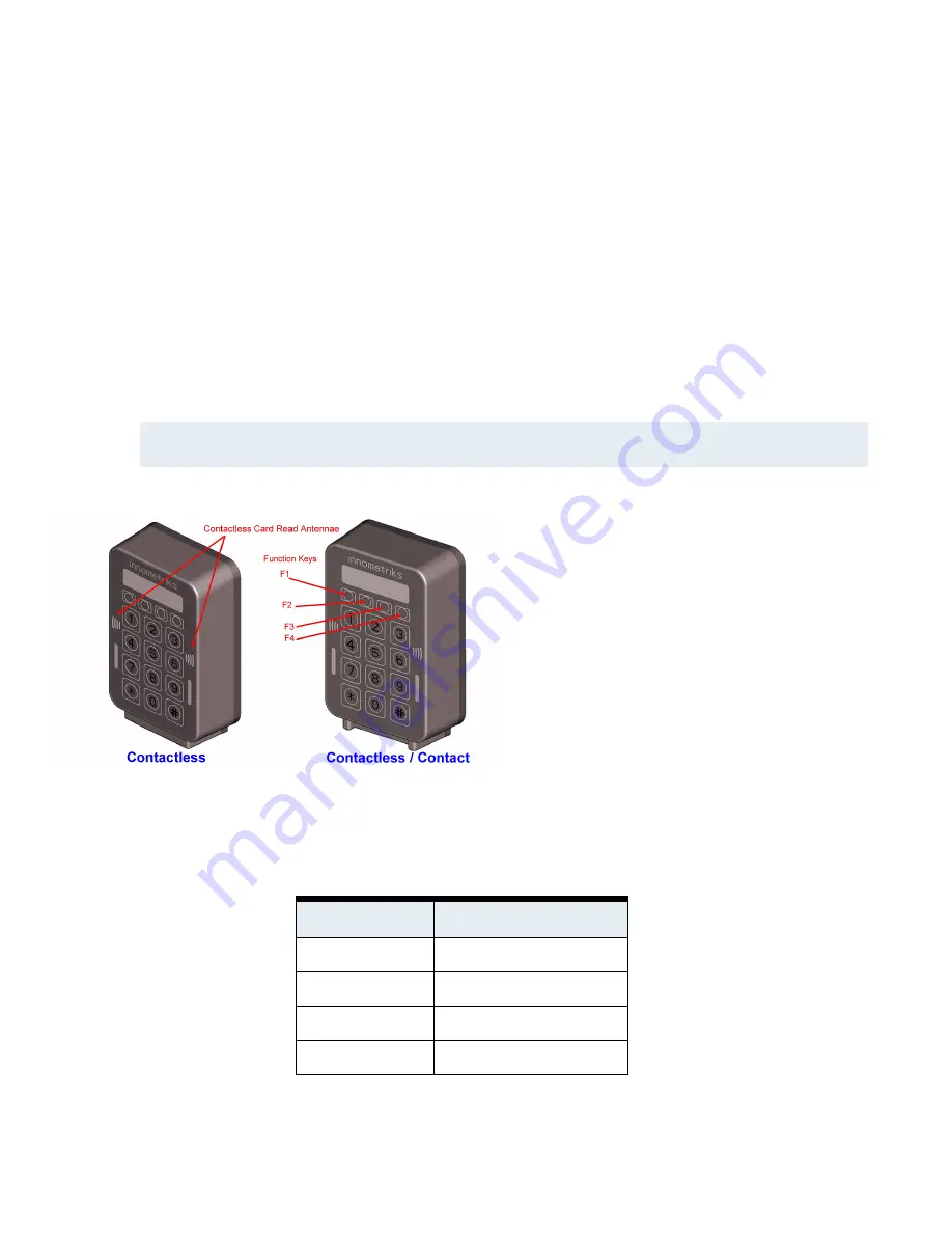
Figure 1:  

Contactless and Contactless/Contact Cheetah SE Reader Models

Figure 1

on

Page 1

shows the indoor contactless

and contactless/contact models of the readers. In
addition, there are outdoor models with the same
dimensions as their indoor counterparts. Over the
keypad of every reader are four function keys, F1 to
F4, from left to right.

Ordering Codes

Product Codes

Description

INN-SECHTA-RF

Indoor: RF Only (Contactless)

INN-SECHTA-CT

Indoor: RF and Contact

INN-SECHTA-RFO

Outdoor: RF Only (Contactless)

INN-SECHTA-CTO

Outdoor: RF and Contact

Table 1:  

Cheetah SE Reader Product Codes

Summary of Contents for Cheetah SE

Page 1: ...eral functionality are contained in the Cheetah SE Reader User Guide Figure 1 Contactless and Contactless Contact Cheetah SE Reader Models Figure 1 on Page 1 shows the indoor contactless and contactle...

Page 2: ...rts 5001 and 5002 In environments with multiple network segments all intermediate routers and switches must be set to forward TCP ports 5001 and 5002 Ethernet is not UL tested Connect Ethernet only wh...

Page 3: ...area when access point actuator is controlled by unit s relay outputs Specifications Network and I O Cables Table 2 Network and I O Cables Usage Cable Description Network Cat5 Ethernet reader to host...

Page 4: ...al Installations The recommended power wiring is Belden 8461 8442 twisted pair The maximum length depends on the wire gauge Installation This section contains the instructions for wiring the readers a...

Page 5: ...the reader housing by two Torx screws located at the bottom of the reader housing as shown in Figure 3 on Page 5 Using a Torx screwdriver remove the two Torx screws from the bottom of the housing 2 S...

Page 6: ...support by inserting two or four screws not supplied into the mounting plate holes see Figure 5 on Page 6 The type of screws depends on the type of support used Figure 5 Mounting Reader to a Support F...

Page 7: ...ectors Description A Ethernet RJ45 connector Provides network connectivity for applications and browser based reader configuration B 9 pin Molex Ground Power Bus RS485 Supervised Inputs See FICAM OSDP...

Page 8: ...cribes the 6 pin Molex keyed connector Since the connector is keyed it can only be inserted into the reader in one configuration that is with pin 6 on the left and with pin 1 on the right as you face...

Page 9: ...able 7 Circuits Wiring Diagrams Wiring for FICAM OSDP Connectivity Figure 9 on Page 9 shows an example of FICAM OSDP wiring Figure 11 on Page 10 shows wiring for supervised inputs Figure 9 FICAM OSDP...

Page 10: ...uts Setting Up the Reader The default or configured settings for the reader are shown in the reader LCD display All settings can be changed through browser based administration except the reader s LCD...

Page 11: ...will redisplay the current firmware version 2 Press key 2 to display the reader s current IP address 3 Press key 3 to display Ethernet Status 4 Press key 4 to display the current Reader Address 5 Pre...

Page 12: ...100 RM address set to 1 RM baud rate set to 9600 Screen brightness and contrast set to normal setting Browser Based Administration This section provides instructions for using browser based administra...

Page 13: ...initial administrator should be changed for security purposes From a web browser connect to the reader s IP Address The login screen displays Figure 12 Login screen Enter the administrator user name...

Page 14: ...or Select Network from the main screen Depending on the reader s setting for Static IP address or DHCP a screen similar to one of the following is displayed Figure 14 Ethernet Screens If you make chan...

Page 15: ...ck the Upload File button to upload the file to the reader and update the firmware The reader will then restart To display options to download upload or restore a configuration file select CONFIGURATI...

Page 16: ...peration is subject to the following two conditions 1 This device may not cause harmful interference and 2 this device must accept any interference received including interference that may cause undes...

Reviews: