Operation Manual
Universal Video Interface Series
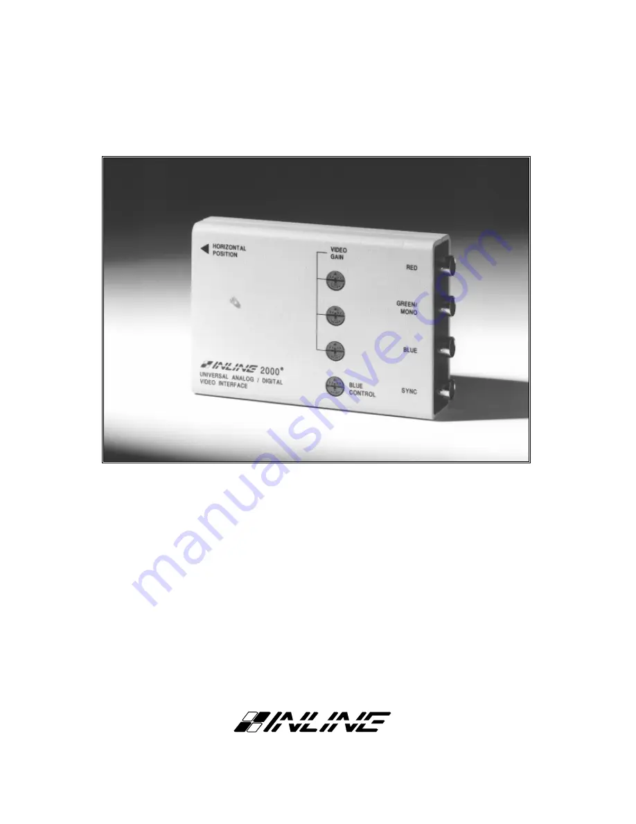
IN2000 Analog / TTL / ECL Video Interface
IN2001 Analog / TTL / ECL Video Interface
®
Page 1: ...Operation Manual Universal Video Interface Series IN2000 Analog TTL ECL Video Interface IN2001 Analog TTL ECL Video Interface...
Page 2: ...tion Diagrams 7 Internal Controls 8 Horizontal Blanking Control 9 Dip Switch Settings 9 Factory Default Settings 9 Sync on Green Output 9 Monochrome Output 9 Disable Enable Horizontal Position Control...
Page 3: ...lay device The IN2000 IN2001 are not scan converters The data projector monitor or other output device must be compatible with the horizontal scan rate output by the computer video card The IN2000 IN2...
Page 4: ...e must be used For more information and a complete listing of IN5100 Monitor Loop Cables see Pages 3 11 Common analog TTL and ECL signals are listed below along with compatible signal formats Analog V...
Page 5: ...SERIES MONITOR LOOP CABLES Unlike Dedicated Video Interfaces which are designed to work with one specific type of computer graphic signal and feature a permanently attached input cable Universal Inter...
Page 6: ...BS output 4 BNC connectors to the data display device s RGBS input using four high resolution BNC cables or a multi conductor RGBS snake The IN7000 IN7100 and IN7600 series high resolution cables are...
Page 7: ...able IN2000 IN2001 Data Projector Monitor IN7000 4 IN7100 4 RGBS Cable Power Supply 12V 500 mA RGBS Input Application Diagram IN2000 IN2001 HORIZONTAL POSITION VIDEO GAIN BLUE CONTROL RED GREEN MONO B...
Page 8: ...input signal will appear at the IN2000 IN2001 outputs as a 1 0 volt signal These controls may be adjusted if required to calibrate the color balance between the red green and blue signals The RED GREE...
Page 9: ...00 UNIVERSAL ANALOG DIGITAL VIDEO INTERFACE IN2000 Top View Horizontal Position Control Red Gain Green Gain Blue Gain Blue Enhancement Control Horizontal Position Control BLUE CONTROL VIDEO GAIN B G R...
Page 10: ...must be taken to avoid static shock to the internal components and or damage to the pins which connect the top and bottom circuit boards The following procedure may be used to access the IN2000 inter...
Page 11: ...anking Control pot located on the bottom of the unit 2 Activate the Blanking Control Pot by turning Dip Switch 10 to ON 3 Adjust the control pot until the image quality improves and all the left hand...
Page 12: ...enables the Blanking Control pot This pot adjusts the video signal left blanking TTL signals only to ensure a clamp to black For more information see Pages 8 9 Dip Switches ON 2 8 9 10 IN2001 INTERNAL...
Page 13: ...7A 25 Pin D NCD 17C IN5173A 26 Pin HD DEC VT420 Kit IN5174A Internal Harness 1 BNC Monochrome IN5132A BNC 4 BNC RGBS or RGsB IN5129A BNC 5 BNC RGBHV or RGsB IN5133A BNC IN2000 IN2001 Input Pin Configu...
Page 14: ...of the following methods to split the signal Looping Method If the local monitor has a Loop Out connector connect the monitor directly to the computer video output Turn the Loop Out termination switc...
Page 15: ...ignals Analog Video 75 ohm impedance Bandwidth 100 MHz 3 dB Rise and Fall Times 4 0 nano seconds Gain Adjustable from 0 8 1 2 Sync Signal Sync output has AGC 4V p p unterminated and 2V p p terminated...
Page 16: ...device connected to the output of the interface may not be compatible with the computer output CGA and EGA signals vary from 15 75 to 24 KHz VGA runs at 31 5 KHz but SVGA can be as high as 48 58 KHz w...
Page 17: ...er must be used the output of the IN2000 will be monochrome The output image from the IN2000 2001 has horizontal black bars throughout the image when interfacing to TTL video signals IN5100 cables end...
Page 18: ...ll of which are expressly disclaimed The information in this manual has been carefully checked and is believed to be accurate However Inline Inc assumes no responsibility for any inaccuracies that may...