background image

                                                                                                                                            WEB  Configuration  Manual 


- 34 -


6.4    Filter Function 

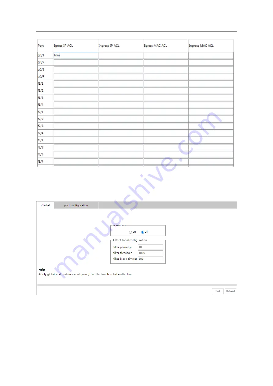
Click 

Network  Security  ->  Filter  Function 

at  navigation  bar  in  order


to  enter  the  filter  function 

global page as following: 


Click 

Set

 at the bottom control bar to finish the global configuration of filter function. 

Click 

Reload

 at the bottom control bar to refresh the global configuration of filter function. 


Click 

“Port Configuration” on the right of “Global”, enter the port configuration page as follows: 

Summary of Contents for InSwitch ISM-P Series

Page 1: ...InHand InSwitch ISM P Series WEB Configuration Manual V1 3 2022 ...

Page 2: ...g Switch 4 2 1 Accessing the Switch Through Web 4 2 2 Initially Accessing the Switch 4 2 2 1 Upgrading to the Web Supported Version 5 2 3 Accessing Switch Through Secure Links 5 2 4 Introduction of Web Interface 6 2 4 1 Top Control Bar 6 2 4 2 Navigation Bar 7 2 4 3 Configuration Display Area 7 2 4 4 Bottom Control Bar 8 Chapter 3 Basic Configuration 9 3 1 System 9 3 2 Global Configuration Mode Ma...

Page 3: ... 23 4 6 802 1X Port Authentication 24 4 6 1 Global 24 4 6 2 Authentication List 25 4 4 3 Port Configuration 25 4 6 4 Statistics 26 4 7 RADIUS 26 4 7 1 Global 26 4 7 2 Service 26 Chapter 5 Time 28 5 1 Basic Setting 28 5 2 NTP 28 Chapter 6 Network Security 29 6 1 DOS Configuration 29 6 1 1 DOS Global Configuration 29 6 2 DHCP Snooping Configuration 29 6 2 1 DHCP Snooping Global Configuration 29 6 2 ...

Page 4: ... 42 7 5 2 VLAN Batch Configuration 43 7 5 3 Port VLAN Configuration 43 7 6 GMRP 44 7 6 1 VLAN List 44 7 6 2 Port Configuration 45 7 6 3 Multicast List 45 Chapter 8 Routing 47 8 1 VLAN Interface and IP Address Configuration 47 8 2 VRRP Configuration 48 8 3 IP Express Forwarding 49 8 4 Static ARP 49 8 5 Static Route 49 8 6 RIP Configuration 50 8 6 1 RIP Configuration 50 8 6 2 RIP Router Entries 51 8...

Page 5: ...63 10 6 ERPS 64 Chapter 11 Diagnostics 65 11 1 System 65 11 1 1 System Information 65 11 2 Report 66 11 2 1 Log Management 66 11 2 2 Log Query 67 11 3 Ports 67 11 3 1 Statistics Table 67 11 3 2 Error Packet Statistics 68 11 3 3 SFP 68 11 3 4 Cable Diagnosis 69 11 3 5 Port Mirroring 69 11 4 LLDP Configuration 70 11 4 1 LLDP Basic Configuration 70 11 4 2 LLDP Interface 70 11 4 3 Topology Discovery 7...

Page 6: ...Table of Contents V Chapter 13 Help 75 13 1 About 75 ...

Page 7: ...80 by default and users can access a switch by entering the IP address directly however switches also support users to change the service port and after the service port is changed you have to use the IP address and the changed port to access switches For example if you set the IP address and the service port to 192 168 2 1 and 1234 respectively the HTTP access address should be changed to http 19...

Page 8: ...ng the Max VLAN numbers to display in Web page 1 1 6 Setting the IGMP Groups number to display in Web page Setting a value between 1 and 100 in the global configuration mode 100 is the max value default value is 15 Command Description ip http web igmp groups igmp groups Setting the IGMP Groups number to display in Web page 1 2 HTTPS Configuration In order to improve the security of communications ...

Page 9: ...port the service port in HTTPS is number 443 User can change the port number through command line in global configuration mode Suggesting the port number is bigger than 1024 so as to avoid the port number collision Command Description ip http secure port portNumber Setting the HTTPS port number ...

Page 10: ...Initially Accessing the Switch When the switch is initially used you can use the Web access without any extra settings 1 Modify the IP address of the network adapter and subnet mask of your computer to 192 168 2 2 and 255 255 255 0 respectively 2 Open the Web browser and enter 192 168 2 1 in the address bar It is noted that 192 168 2 1 is the default management address of the switch 3 If the IE br...

Page 11: ...re Links The data between the WEB browser and the switch will not be encrypted if you access switch through common HTTP To encrypt these data you can use the secure links which are based on the secure sockets layer to access the switch To do this you should follow the following steps 1 Connect the console port of the switch with the accessory cable or telnet to the management address of the switch...

Page 12: ...Control Bar Save All Write the current settings to the configuration file of the device It is equivalent to the execution of the write command The configuration that is made through Web will not be promptly written to the configuration file after validation If you click Save the unsaved configuration will be lost after rebooting English The interface will turn into the English version Chinese The ...

Page 13: ...wse the flux of the current port you have to click Diagnostics and then Ports Statistics Table Note The limited user can only browse the state of the device and cannot modify the configuration of the device If you log on to the Web with limited user s permissions only System will appear 2 4 3 Configuration Display Area The configuration display area shows the state and configuration of the device ...

Page 14: ...oes not mean that the configuration is saved in the configuration file To save the configuration you have to click Save on the top control bar Reload Refresh the content shown in the current configuration area Create Create a list item For example you can create a VLAN item or a new user Delete Delete an item in the list Go Back Go back to the previous level configuration page Clear Clear the cont...

Page 15: ...s below The system message will be displayed in the dialog box The default name of the device is Switch You can enter the new hostname in the text box and then click Set in the bottom control bar 3 2 Global Configuration Mode Management Interface If you click Basic Setting Global Network Config in the navigation bar the page appears as shown as below ...

Page 16: ... will appear on this page 3 3 Port Configuration If you click Basic Setting Port Configuration in the navigation bar the Port Configuration page appears as shown as below figure You can change the status speed duplex mode and flow control of a port on this page Note Port link switching might happen if modifying port s speed or duplex mode Network communication might be affected 3 4 Auto Shutdown C...

Page 17: ...urrent running version and ROM version could be checked at this page Click Export to export current running version to computer Choose the to be updated software version and click Update to change system s software version on Software Update Column Note The updated system s software will be valid only if the device is restarted 3 6 Load Save If you click Basic Setting Load Save in the navigation b...

Page 18: ... bar the page appears as shown as below figure You can choose Reboot to reboot the switch or choose Clear MAC Address Table Clear ARP Table Clear port counters 3 8 Factory Settings On this page you can reset the equipment to factory setting click the Restore button to reset to factory setting ...

Page 19: ...ment If you click Security User Management in the navigation bar the page appears as shown as below figure Click Modify to change user s configuration at this page and click Delete at the bottom bar to delete the selected user Click Create at the bottom bar to enter the following page ...

Page 20: ...ollowing Click Modify to change user group s configuration at this page Select user and click Delete at the bottom bar to delete the selected user group Click Detail to check and configure members of group as following Click Create at the bottom bar of group management page to enter the following page Fill in configuration at every configuration column and click Set at the bottom bar to create a n...

Page 21: ...click Set at the bottom bar to create new password regulation 4 1 4 Author Rule Management Click Security User Management in order and then click Author Management to open configuration page as following Click Modify to change author rules at this page Click Delete at the bottom bar to delete author rules Click Create at the bottom bar to enter the following page Fill in configuration at every con...

Page 22: ...rules Click Create at the bottom bar to enter the following page Fill in configuration at every configuration column and click Setup at the bottom bar to create new authentication rules 4 2 Management Access 4 2 1 Server HTTP HTTPS SSH and SNMP could be configured at this page Click Security Management Access Server at navigation bar in order to enter service configuration page Click HTTP at this ...

Page 23: ... Access SNMPv1 v2 Community at navigation bar in order to enter configuration page as following Click Modify to change the feature of SNMP Community Click Create to create a new SNMP Community Click Delete to delete the selected SNMP Community Click SNMP Host to switch to the SNMP Host configuration page Click Create to create a new SNMP Host ...

Page 24: ... change the features of SNMPv3 Group Configuration Click the Reload at the bottom control bar to refresh the configuration information of SNMPv3 Group Click Create to create a new configuration for SNMPv3 Group Click SNMPv3 User Config to enter the following configuration page Click Modify to change the features of SNMPv3 User Configuration Click Reload at the bottom control bar to refresh the inf...

Page 25: ...ine Interface Click Security Management Access CLI at navigation bar in order to enter GLOBAL configuration page as following Terminal s overtime time could be configured at this page and if configured as 0 it means there would be never overtime Click Login Banner to enter the following page Terminal s Login Banner could be configured at this page ...

Page 26: ...mation of that port Click Modify to change the selected binding items of the IP MAC Click Reload to refresh the configuration of the IP MAC binding Click Create to create a new IP MAC binding item Click Delete at the bottom control bar to delete the selected IP MAC binding item 4 3 2 Static MAC Filter Mode Click Security Port Security at navigation bar in order and then click Static MAC Filter Mod...

Page 27: ...on Mode could be configured at this page 4 3 3 Static MAC Filter Click Security Port Security at navigation bar in order and then click Static MAC Filter to enter configuration page as following Click Detail to check the interface s static MAC filtration items ...

Page 28: ...ynamic MAC Mode Click Security Port Security at navigation bar in order and then click Dynamic MAC Mode to enter configuration page as following Interface s Dynamic MAC Mode could be configured at this page 4 4 Switchport Protect Click Security Switchport Protect at navigation bar in order to enter configuration page as following Set the Port Protect Group at this page click Set at the bottom cont...

Page 29: ...ntrol bar delete the selected port protect group Click Create at the bottom control bar enter the Port Protect Group Creating page Click Set at the bottom control bar to finish the setting Click Reload at the bottom control bar refresh the Port Protect Group Creating page Click Go Back at the bottom control bar go back to the Port Protect List page 4 5 Keepalive Click Security Keepalivel at naviga...

Page 30: ...ick Reload at the bottom control bar refresh the port setting information 4 6 802 1X Port Authentication 4 6 1 Global Click Security 802 1X Port Authentication Global at navigation bar in order to enter configuration page as following Configure the enabling disabling operations of 802 1X port authentication at this page ...

Page 31: ...l bar to delete the selected port authentication list Click Create to create new authentication entry 4 4 3 Port Configuration Click Security 802 1X Port Authentication Port Configuration at navigation bar in order to enter configuration page as following You could configure interface s enabling disabling 802 1x port authentication authentication type authentication mode method and etc at this pag...

Page 32: ...mation of 802 1x messages could be checked at this page 4 7 RADIUS 4 7 1 Global Click Security RADIUS Global at navigation bar in order to enter configuration page as following Max Number of retransmits of radius overtime NAS and Radius Server Key could be configured at this page 4 7 2 Service Click Security RADIUS Service at navigation bar in order to enter configuration page as following ...

Page 33: ...t the bottom control bar to finish the setting Click Reload at the bottom control bar refresh the authentication port and accounting port information Click Delete at the bottom control bar to delete the selected authentication port and accounting port information of RADIUS Server Click Create to create new radius server items ...

Page 34: ...wing Click Reload to refresh the current displayed system time System s time zone could be configured at this page Select Set Time Manually to set system time manually 5 2 NTP Click Time NTP at navigation bar in order to enter configuration page as following NTP server s IP address of NTP Network Time Synchronization could be configured at this page ...

Page 35: ...uration Click Network Security DOS Global at navigation bar in order to enter DOS global configuration page as following You could set or cancel the related Preventing DOS Attack according to needs Click Set to save configuration 6 2 DHCP Snooping Configuration 6 2 1 DHCP Snooping Global Configuration ...

Page 36: ...enabled After the interface binding relationship s backup TFTP server is configured binding relationship would be copied to server by TFTP protocol After switch restarted it would download binding list from TFTP server automatically to ensure network s normal operation When configuring backup interface binding relationships save file name on TFTP server Therefore different switches can copy their ...

Page 37: ...nfigured for a physical port the switch will refuse to forward all the ARP messages In a VLAN where IP source addresses are monitored if the source MAC and IP addresses of the IP messages received by all the physical ports in the VLAN do not match the MAC and IP address binding relations configured for the ports the messages cannot be processed The binding relations configured for the ports may be...

Page 38: ...y the latter will be updated based on the former The MAC address is the only one index for binding entries of a port Click Create to create entries for binding manually configured DHCP Snooping ports Note Binding entries can be created only if enabling DHCP Snooping protocol 6 3 Access Control List 6 3 1 IPv4 Rules Click Network Security Access Control List IPv4 Rules at navigation bar in order to...

Page 39: ...trol list 6 3 2 MAC Rules Click Network Security Access Control List MAC Rules at navigation bar in order to enter MAC rules page as following Click Create at the bottom control bar to create a MAC access control list Click Delete to delete the selected access control list 6 3 3 Assignment Click Network Security Access Control List Assignment at navigation bar in order to enter distribution page o...

Page 40: ...r the filter function global page as following Click Set at the bottom control bar to finish the global configuration of filter function Click Reload at the bottom control bar to refresh the global configuration of filter function Click Port Configuration on the right of Global enter the port configuration page as follows ...

Page 41: ...WEB Configuration Manual 35 Click Set at the bottom control bar to finish the configuration of port Click Reload at the bottom control bar refresh the port configuration of filter function ...

Page 42: ...rol and unicast storm control configuration pages 7 1 1 Broadcast Storm Control Through the dropdown boxes in the Status column you can decide whether to enable broadcast storm control on a port In the Threshold column you can enter the threshold value of the broadcast packets The legal threshold range for each port is given behind the threshold 7 1 2 Multicast Storm Control ...

Page 43: ... each port is given behind the threshold 7 1 3 Unicast Storm Control Through the dropdown boxes in the Status column you can decide whether to enable unicast storm control on a port In the Threshold column you can enter the threshold value of the unicast packets The legal threshold range for each port is given behind the threshold 7 2 Port Rate Limits Click Switching Port Rate Limits at navigation...

Page 44: ... be configured according to ratio or switch s defined unit 7 3 MAC Address Table Click Switching MAC Address Table at navigation bar in order to enter static MAC address table as following Static MAC address VLAN ID and index are shown on the page Click Modify or Create to enter static MAC address configuration page and do modifications on configured static MAC address table ...

Page 45: ...IGMP Snooping 7 4 1 IGMP Snooping Configuration Click Switching IGMP Snooping at navigation bar in order and select IGMP Snooping tab page to enter IGMP Snooping configuration page as following Whether switch forwarding unknown multicast whether enabling IGMP Snooping and whether taken as IGMP s Querier can be configured at this page ...

Page 46: ...iguration can be done Through Web up to 8 physical ports can be set on each IGMP snooping VLAN Click Delete a selected IGMP Snooping VLAN can be deleted When an IGMP Snooping VLAN is created its VLAN ID can be modified but when the IGMP Snooping VLAN is modified its VLAN ID cannot be modified You can click and to delete and add a routing port 7 4 3 Static Multicast Mac Address Configuration Click ...

Page 47: ...t Multicast List tab page to enter multicast member list configuration page as following The multicast groups in current network and ports set where every group member exists counted by IGMP Snooping are shown on this page Click Reload to refresh the contents in the list Note By default a multicast list can display up to 15 VLAN items You can modify the number of multicast items by running ip http...

Page 48: ...ure more VLAN through Web please login switch by Console port or Telnet to enter global configuration mode and use command ip http web max vlan to modify maximum shown VLAN quantity Click Create or Modify to enter VLAN configuration page If you want to create a new VLAN enter a VLAN ID and a VLAN name the VLAN name can be null Through the port list you can set for each port the default VLAN the VL...

Page 49: ...fore VLAN to be deleted it should be added first 7 5 3 Port VLAN Configuration Click Switching VLAN at navigation bar in order and select Port VLAN tab page to enter port VLAN configuration page as following This page shows all ports PVIDs modes allowed VLAN range and VLAN range without tag Click Modify to change port s VLAN feature configuration VLAN allowed configuration and VLAN untagged config...

Page 50: ...LAN allowed and VLAN untagged Please add first before do delete operation Please do not use Enter key 7 6 GMRP 7 6 1 VLAN List Click Switching GMRP VLAN List at navigation bar in order to enter port VLAN configuration page as following ...

Page 51: ...l bar to refresh the list Click Create at the bottom control bar create GMRP VLAN configuration 7 6 2 Port Configuration Click Switching GMRP Port Configuration at navigation bar in order to enter Port Configuration page as following Click Set at the bottom control bar finish the configuration 7 6 3 Multicast List ...

Page 52: ...ast List at navigation bar in order to enter Multicast List page as following This page shows the VLAN ID multicast MAC address and member port information of GMRP multicast list Click Reload at the bottom control bar refresh the multicast list information ...

Page 53: ...enter configuration page as following Click Modify to enter relative VLAN interface items to do the modification Click Create to create a new VLAN interface items Click Delete to delete the selected VLAN interface items You can change the VLAN name when you click the Create bottom It s cannot change VLAN name when click Modify just can do the VLAN related items modification ...

Page 54: ...tion Click Routing VRRP Configuration at navigation bar in order and then enter VRRP List page as following Click Reload at the bottom control bar refresh VRRP list information Click Delete at the bottom control bar delete the selected VRRP configuration information Click Create at the bottom control bar to enter new VRRP configuration page ...

Page 55: ...l bar to finish the setting of IP Express Forwarding Click Reload at the bottom control bar refresh the information of IP Express Forwarding information 8 4 Static ARP Click Routing Static ARP at navigation bar in order and then enter configuration page as following Click Modify to modify the current Static ARP Click Delete to delete the selected Static ARP items Click New to create a new Static A...

Page 56: ...itches have the static route configuration page 8 6 RIP Configuration 8 6 1 RIP Configuration Click Routing RIP Configuration at navigation bar in order and then enter RIP configuration page as following You should have created a RIP process firstly before do the RIP entry configuration When Edit the RIP process can create the new RIP process or delete it also Click Create to create a new RIP proc...

Page 57: ...he selected RIP Router Entries page Click Create to create a new RIP Router Entries of selected RIP process 8 7 OSPF Configuration 8 7 1 OSPF process Click Routing OSPF Configuration at navigation bar in order and then click OSPF Process to enter configuration page as following You should have created a OSPF process firstly before to do the OSPF Router Entries configuration otherwise cannot do any...

Page 58: ...ter Entries to enter OSPF Router Entries configuration page as following Enter the OSPF process ID which was created already click Set to enter the selected OSPF Router Entries configuration page Click Create to create the OSPF Router Entries of OSPF process selected The format that the Area column can accept is an integer or IP address ...

Page 59: ...in order and then enter the global configuration page as following You can do the setting of Schedule Policy Default CoS Value and Trust Priority in the QoS Global page 9 2 Port Configuration Click QoS Priority Port Configuration at navigation bar in order and then enter the configuration page as following ...

Page 60: ... 1D p Mapping Click QoS Priority 802 1D p Mapping at navigation bar in order and then enter the configuration page as following Click Set to save all 802 1D p mapping configurations 9 4 IP DSCP Mapping Click QoS Priority IP DSCP Mapping at navigation bar in order and then enter the configuration page as following ...

Page 61: ...nfiguration Note The number of table parameter may be different between different device model 9 5 Queue Management Click QoS Priority Queue Management at navigation bar in order and then enter the configuration page as following Click Set to save all configuration Note If one Queue ID set the bandwidth weight to Zero value then the weight value of the other queue ID must must be set to Zero ...

Page 62: ...d then enter the link aggregation configuration port channel page as following Click Modify to modify the member port and aggregation mode of the aggregation port Click Create to create a new aggregation group As much as 32 aggregation groups can be configured through Web Each group can configure at most 8 physical port aggregations Click Delete to delete the selected aggregation group ...

Page 63: ... Channel Global Loading Balance Some models support link aggregation load balancing configuration and others not but the configuration can be done in the global configuration mode ISM P Layer 3 model can support the aggregation group based load balancing configuration You can use different aggregation groups to set different aggregation modes 10 2 Backup Link 10 2 1 Backup Link Global Configuratio...

Page 64: ...this system 2 The preemption mode of the link backup group decides the policy of the primary port and the backup port selecting forwarding packets 10 2 2 Link Backup Protocol Port Configuration Click Redundancy Backuplink Port Configuration at navigation bar in order and then enter the backup link protocol port configuration page as following The page lists the member port has joined the backup li...

Page 65: ...cannot be configured other port as backup 10 3 Spanning Tree 10 3 1 Global Click Redundancy Spanning Tree Global at navigation bar in order and then enter the spanning tree global configuration page as following The page can configure the local STP protocol such as protocol type spanning tree priorities etc Click Set to save configuration 10 3 2 MSTP 10 3 2 1 MST Global Click Redundancy Spanning T...

Page 66: ... and then click the MST Instance to enter the configuration page as following This page shows the VLAN Mapping priority and etc of every instance Click Reload at the bottom control bar refresh the MST Instance information Click Modify on the right of the table configure the instance On this page the path cost and priority can be configured And click Set at the bottom control bar to save the config...

Page 67: ...nabling status which can be configured After configuration click Set at the bottom control bar to save the configuration 10 3 3 2 Port Status Click Redundancy Spanning Tree Ports at navigation bar in order and then click the Port Status tab to enter the status page as following The page lists the port information and usage status of spanning tree Click Reload can refresh the data 10 4 EAPS ether r...

Page 68: ...1 The EAPS ring ether ring number the system supported is 32 2 After the EAPS ring ether ring configured the ring ID node type and CONTROL VLAN cannot be changed If they needed to be changed please delete the EAPS ether ring and create new Click Create at the bottom control bar on the EAPS ether ring page or click Modify on the right enter the EAPS ring ether ring configuration page In the drop do...

Page 69: ...has configured its Domain ID Ring ID Ring Type Node Type and Control VLAN cannot be changed If these parameters need to be configured please delete this ring and re create it Click New or Modify on the right of the entry in MEAPS network ring list and enter MEAPS configuration page Master node and the transit node can only be configured in the the primary ring Primary node transit node and edge no...

Page 70: ...orts ERPS single ring configuration 2 Max 8 ERPS ring node 3 Once one ERPS has been configured its ID ring ID and control Vlan cannot be configured If these parameters need to be configured please delete this ring and re create it Click Create at the bottom control bar or click Modify on the right of the item enter the ERPS configuration page as following The ring ID of ERPS can be from 1 to 7 Aft...

Page 71: ...Configuration Manual 65 Chapter 11 Diagnostics 11 1 System 11 1 1 System Information Click Diagnostics System System Information at navigation bar in order and then enter the configuration page as following ...

Page 72: ...ation such as CPU utilization task information and etc 11 2 Report 11 2 1 Log Management Click Diagnostics Report Log Manage at navigation bar in order and then enter the configuration page as following When Enabling the log server was selected the device will transmit the log information to the designated server In this case you need enter the address of the server in the Web Configuration ...

Page 73: ... in the Size of the system log buffer textbox and select the grade of the cached log in the Grade of the cache log information dropdown box 11 2 2 Log Query Click Diagnostics Report Log Query at navigation bar in order and then enter the configuration page as following Note If you need more information you can Query it by setting the log level and log time Do not set the log time means that the qu...

Page 74: ...page as following This page shows the communication data including received discard received error packets FCS packets Jabber packets received oversize packets received undersize packets transmitted discard transmitted error packets transmitted oversize packets etc Click Clear at the bottom control bar to clean all the error packet statistics information 11 3 3 SFP Click Diagnostics Port SFP at na...

Page 75: ...he diagnosis 11 3 5 Port Mirroring Click Diagnostics Port Port Mirroring at navigation bar in order and then enter the configuration page as following Click the dropdown box right of the Mirror Port and select a port to be the destination port of mirror Click the checkbox and select the mirroring source port RX The received packets will be mirrored to the destination port TX The transmitted packet...

Page 76: ... disabled HoldTime refers to the ttl value for transmitting the LLDP message The default value is 120s Reinit refers to the transmission delay of LLDP The default value is 2s 11 4 2 LLDP Interface Click Diagnostics LLDP LLDP Interface at navigation bar in order and then enter the LLDP port configuration page as following LLDP port configuration can enable or disable the port transmitting LLDP pack...

Page 77: ...Manual 71 Click Diagnostics LLDP Topology Discovery at navigation bar in order and then enter the LLDP topology discovery and configuration page as following The page lists the devices that have been found by this device ...

Page 78: ...for Number of ICMP packets ICMP timeout default value is 5 seconds BTW you also can configure the DHCP database parameters such as server IP address database file name time stamp appends to filename 12 1 2 DHCP Server Pool Configuration Click Advanced DHCP Server Pool at navigation bar in order and then enter the DHCP server pool configuration page as following The page lists the DHCP server pool ...

Page 79: ... Configuration at navigation bar in order and then click the Global tab page enter the SFlow global configuration page as following You can configure the Agent IP address on this page the default value of SFlow Version is 5 default value of Maximum Header Size is 20 maximum number is 128 Click Port tab to enter the SFlow port configuration page as following ...

Page 80: ...on your requirement when it is setting to be enabled 12 2 2 SFlow Statistics Click Advanced SFlow Statistics at navigation bar in order and then click the Poller tab page enter the SFlow poller information page as following Click Advanced SFlow Statistics at navigation bar in order and then click the Sampler tab page enter the SFlow poller information page as following ...

Page 81: ...ter 13 Help 13 1 About Click Help About at navigation bar in order enter the About page as following The information will shown in this page which are included IOS version messages company website contact telephone and etc End of File ...

Reviews: