


41
Specifications
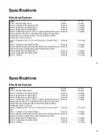
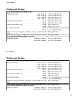
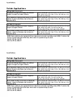
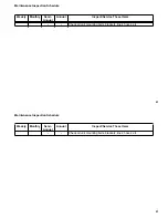
Electrical System
Fuses
12 Volt
24 Volt
Fuse 1: Power Supply Circuit
5 amps
5 amps
Fuse 2: Condenser Fan Motor (CFM1)
15 amps
10 amps
Fuse 3: Evaporator Fan Motor (EF1)
15 amps
10 amps
Fuse 4: Evaporator Fan Motor (EF2)
15 amps
10 amps
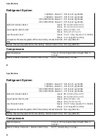
Fuse 5: Compressor Clutch 1 (CCL1), Liquid Injection Switch (LIS),
Liquid Injection Valve(LIV), Host Defrost Hot Solenoid Valve (PS1),
Compressor otor Contactor (CMC), Heat Pilot Solenoid (PS5),
Compressor Clutch 2 (CCL2)
20 amps
10 amps
Fuse 6: Condenser Fan 1, 2 (CF1, CF2) Heater 1, Heater 2 (HT1,
HT2)
10 amps
7.5 amps
Fuse 7: Condenser Fan Motor (CFM2)
15 amps
10 amps
Fuse 8: Remote Liquid Solenoid Valve (PS2), Host Liquid Solenoid
Valve (PS3), Remote Defrost Hot Gas Solenoid Valve (PS4)
20 amps
10 amps
Fuse 9: Evaporator Fan Motor (EF3)
15 amps
10 amps
Fuse 10: Evaporator Fan Motor (EF4)
15 amps
10 amps
Fuse 11: Heaters
10 amps
7.5 amps
41
Specifications
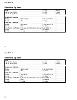
Electrical System
Fuses
12 Volt
24 Volt
Fuse 1: Power Supply Circuit
5 amps
5 amps
Fuse 2: Condenser Fan Motor (CFM1)
15 amps
10 amps
Fuse 3: Evaporator Fan Motor (EF1)
15 amps
10 amps
Fuse 4: Evaporator Fan Motor (EF2)
15 amps
10 amps
Fuse 5: Compressor Clutch 1 (CCL1), Liquid Injection Switch (LIS),
Liquid Injection Valve(LIV), Host Defrost Hot Solenoid Valve (PS1),
Compressor otor Contactor (CMC), Heat Pilot Solenoid (PS5),
Compressor Clutch 2 (CCL2)
20 amps
10 amps
Fuse 6: Condenser Fan 1, 2 (CF1, CF2) Heater 1, Heater 2 (HT1,
HT2)
10 amps
7.5 amps
Fuse 7: Condenser Fan Motor (CFM2)
15 amps
10 amps
Fuse 8: Remote Liquid Solenoid Valve (PS2), Host Liquid Solenoid
Valve (PS3), Remote Defrost Hot Gas Solenoid Valve (PS4)
20 amps
10 amps
Fuse 9: Evaporator Fan Motor (EF3)
15 amps
10 amps
Fuse 10: Evaporator Fan Motor (EF4)
15 amps
10 amps
Fuse 11: Heaters
10 amps
7.5 amps
Summary of Contents for Thermo King V-520 10
Page 2: ......
Page 4: ...2 2...
Page 6: ...Introduction 4 Introduction 4...
Page 14: ...Safety Precautions 14 Safety Precautions 14...
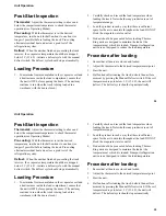
Page 40: ...Unit Operation 40 Unit Operation 40...
Page 48: ...Specifications 48 Specifications 48...
Page 52: ...Maintenance Inspection Schedule 52 Maintenance Inspection Schedule 52...
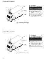
Page 58: ...Loading and Enroute Inspections 58 Loading and Enroute Inspections 58...
Page 60: ...Serial Number Locations 60 Serial Number Locations 60...
Page 62: ...Warranty 62 Warranty 62...
Page 72: ...72 72...
Page 73: ......