Triton Go Product Manual |
Wiring and Connections
INGENIA | 05/29/2017
72
68
http://doc.ingeniamc.com/display/EMCL/encoder
69
http://ingeniamc.com/software#motionlab
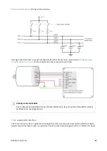
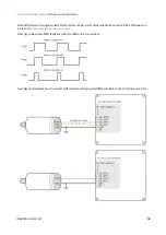
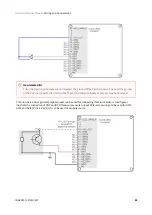
Digital encoders with single ended 24 V outputs
Triton Go Servo Drive can also interface single ended digital encoders with output voltages higher than 5 V, for
instance 24 V PLC level encoder. With the use of series connected limiting resistors, Triton Go is able to read
encoder counts correctly while the inputs are correctly protected.
A 4.7 k
Ω
, 1/4 W resistor should be used in series with the ENC_X+ input and leave the ENC_X- (inverting)
floating.
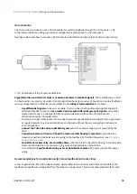
7.4.4 Analog encoder (Sin-Cos encoder) interface
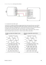
The Triton Go Servo Drive can use analog encoder (also known as Sin-Cos encoder) as position and velocity
feedback element. This sensor provide a pair of quadrature sine and cosine signals as the motor moves, which
frequency depends on the motor speed. The signals may be generated by optical or magnetic means. For noise
immunity the signals are typically transmitted differentially from the encoder to the sensor interface
electronics.
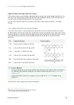
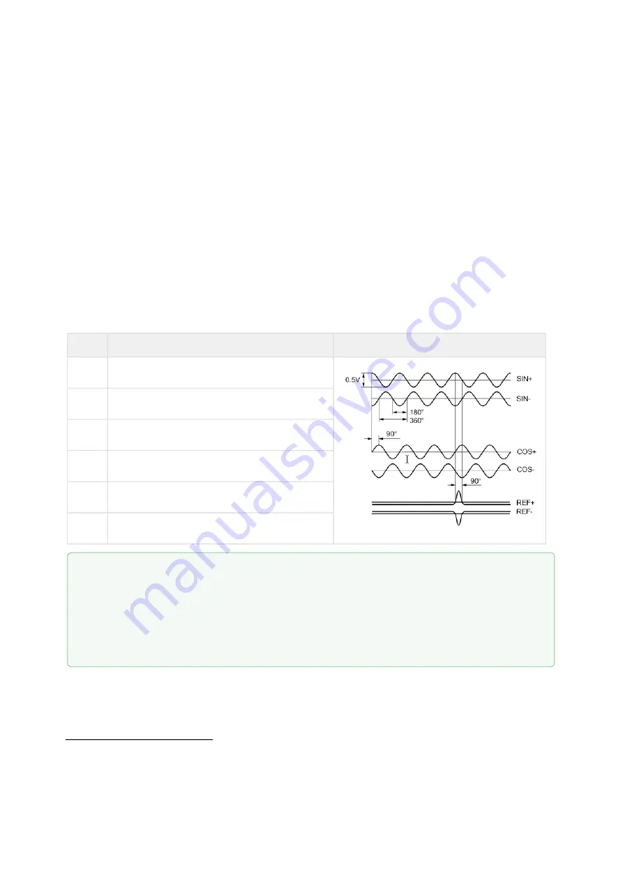
Pin
Signal description
Signal example
SIN+
Sine wave with 2.5 V offset and 0.5 Vpp
SIN-
Same as SIN+, but with 180º phase shift
COS+
Cosine with 2.5 V offset and 0.5 Vpp
COS-
Same as COS+, but with 180º phase shift
REF+
One sine half wave per revolution as index pulse
REF-
Same as REF+, but with 180º phase shift
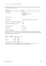
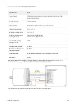
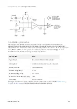
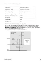
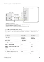
Next table summarizes analog encoder inputs main features.
Sin-Cos calibration
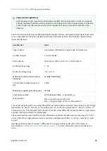
Analog encoder signals are not always a perfect sine and cosine. For this reason, Triton Go includes sin-
cos calibration and adjustment parameters. For further information see the E-Core
An automatic calibration based on Lissajous curves is included in
, allowing an easy
adjustment.

