


TITAN GO Product Manual |
Wiring and Connections
INGENIA | 2022-07-14 08:35:14
75
•
•
•
•
•
•
•
•
•
•
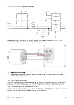
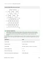
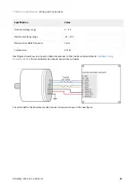
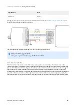
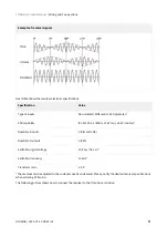
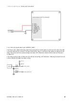
Next figure illustrates how to connect a DC tachometer with differential output to the Titan Go Servo Drive.
7.5.8 Feedback wiring recommendations
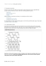
Signal distortion and electrical noise is a common problem in feedback signals
. These problems can result in a
bad position or velocity calculation for both digital feedbacks (gain or loss of counts) and analog feedbacks (wrong
voltage levels).To minimize these problems some
wiring recommendations
are shown:
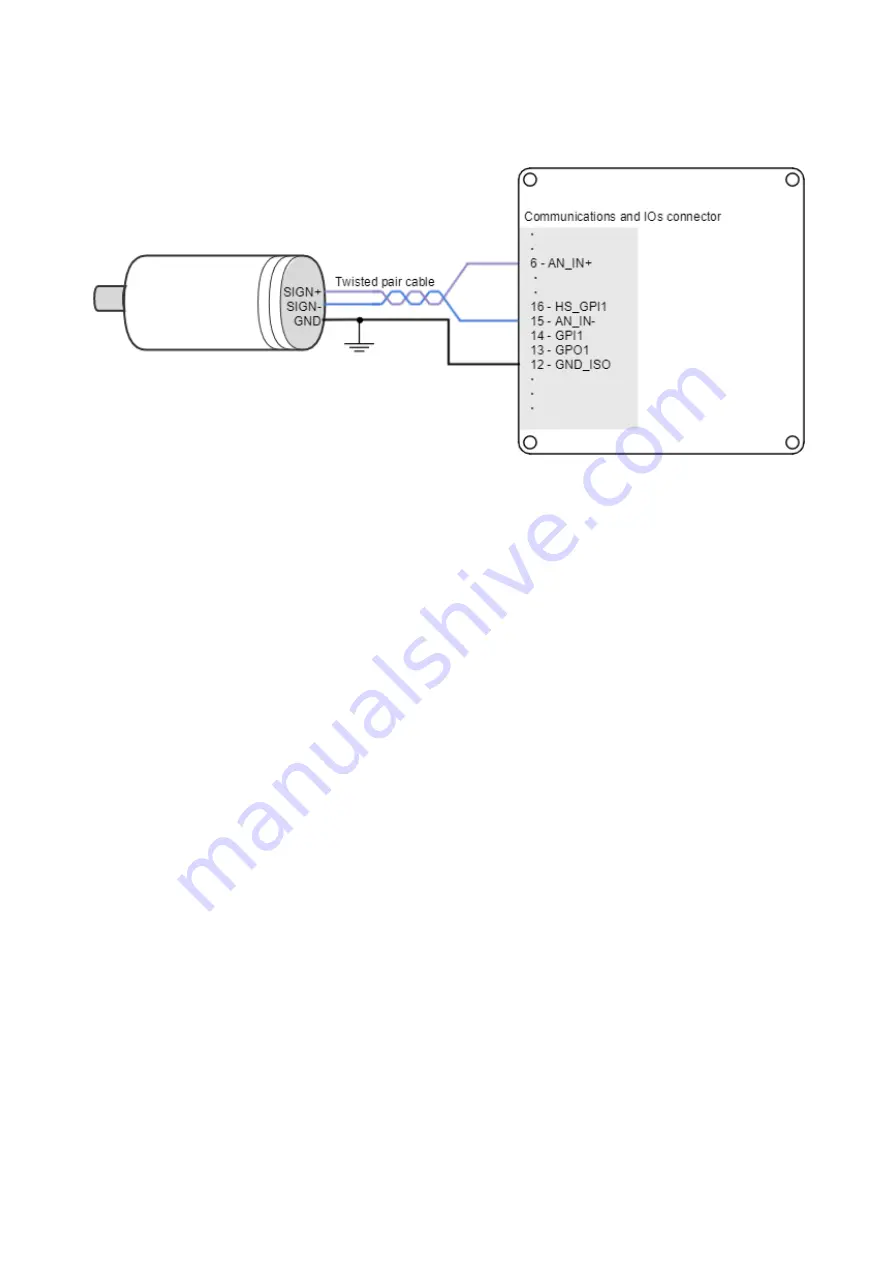
Use differential signals
whenever is possible. That is, connect both positive and negative signals of
differential feedback sensors.
Use a twisted pair for each differential group of signals
and another
twisted pair for the +5 V supply and GND. Twisted-pairs help in elimination of noise because disturbances
induced in twisted pairs
Twisted-pairs help in elimination of noise due to electromagnetic fields by twisting the two signal leads at
regular intervals. Any induced disturbance in the wire will have the same magnitude and result in error
cancellation.
Connect the Titan Go and encoder GND signals
even if the encoder supply is not provided by the drive.
Connection between Titan Go PE and the motor metallic housing is essential
to provide a low
impedance path and minimize noise coupling to the feedback. For further information, see
For better noise immunity, use shielded cables,
with the shield connected to PE only in the drive side.
Never use the shield as a conductor carrying a signal, for example as a ground line.
It is essential to
keep feedback wiring as far as possible from motor,
AC power and all other power wiring.
7.5.8.1 Recommendations for applications witch close feedback and motor lines
In some applications, like in the subsea market, where additional connectors and cables are a problem, the
feedback cannot be wired separately from the motor and power lines. This creates noise problems that could result
in hall sensors wrong commutation errors or encoder loss of counts. For these applications we recommend:
Use a common mode choke on the motor phases. This single action can reduce common mode noise
drastically and will solve most problems. See recommended wiring in
Motor and shunt braking resistor
Ensure the motor housing is well connected to protective earth and the system chassis (PE).
If possible, minimize power supply voltage. This will also minimize the electromagnetic noise generated by
the motor switching.
Add additional RC low pass filters on the feedback inputs. The filter should attenuate at a frequency above
the maximum speed signal to prevent loss of counts and signal distortion. Preferably use resistors with low
Summary of Contents for Titan GO
Page 19: ...TITAN GO Product Manual Product Description INGENIA 2022 07 14 08 35 14 19 ...
Page 56: ...TITAN GO Product Manual Wiring and Connections INGENIA 2022 07 14 08 35 14 56 ...
Page 89: ...TITAN GO Product Manual Wiring and Connections INGENIA 2022 07 14 08 35 14 89 ...
Page 101: ...TITAN GO Product Manual Wiring and Connections INGENIA 2022 07 14 08 35 14 101 ...


