


Everest CORE - Product Manual |
Application Guide
INGENIA | 08/01/2019
38
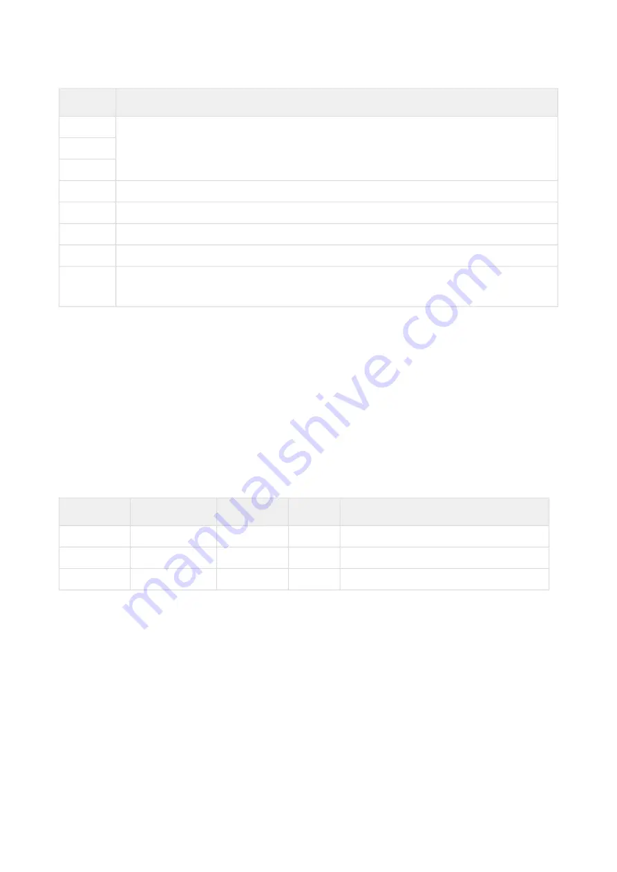
Signal
Description
OUTPUT_2
OUTPUT_3
OUTPUT_4
GPO1
To be connected to pin 55 of Everest CORE Interface connector
GPO2
To be connected to pin 56 of Everest CORE Interface connector
GPO3
To be connected to pin 57 of Everest CORE Interface connector
GPO4
To be connected to pin 43 of Everest CORE Interface connector
GND_D
Logic supply reference voltage. To be connected to pins 39, 59 or 60 of Everest CORE Interface
connector
Design Notes
•
The suggested MOSFETs do not require gate biasing.
•
Also, the suggested MOSFETs feature short-circuit, overload, over-temperature and inverse polarity
protection.
•
This solution should allow driving small inductive loads with no need of a wheeling diode.
•
When driving loads in open collector configuration, only the negative terminal of the load must be
connected to the output. Although it is an output, it will work by sinking current. The positive terminal of the
load would be connected to a power source which Ground terminal is shared with Everest CORE.
•
When using the load in push-pull configuration, the 1 k
Ω
resistor set the output impedance and limit the
current. In this case, note that the polarity of the GPOx signal coming from Everest CORE will be inverted in
the output.
Bill of materials
Designator
Part Number
Manufacturer Package
Value / Description
D1, D2, D3, D4
1N4148WS
Fairchild
SOD-323F Diode rectifier 75 V, 150 mA
R1, R2, R3, R4
RMCF0402FT1K00 Stackpole
0402
Thick film resistor, 1 k
Ω
, 1 % tolerance, 1/16 W
Q1, Q2, Q3, Q4 ZXMS6004FFTA
Diodes Inc.
SOT-23F
N-channel MOSFET , 60 V, 1.3 A
Mechanical Brake Output
Because of its similarities, the same circuit as the one proposed in the Shunt Braking Resistor Transistor section
could be used. However, for cost and space optimisation, the following circuit is proposed. This would provide a 24
V tolerant open collector output for driving a mechanical brake of the solenoid type.


