background image

EonNAS 1000 Series Hardware Manual 

19 

1.1.6 

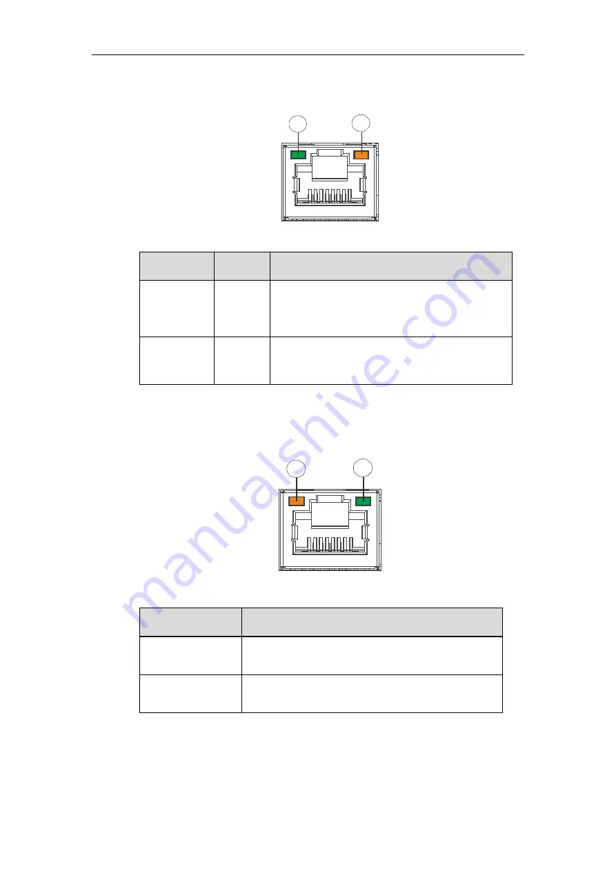
Rear Panel Ethernet Port LEDs 

1

2


No. & Item 

Color 

Status 

1. Link 

Status LED 

Green 

Steady green

 indicates connection established 

Off: indicates connection not established 

2. Activity 

LED 

Amber 

Blinking amber

 indicates data transfer activity 


1.1.7 

1Gb iSCSI Expansion Host Ports 

1

2


Position 

Status 

1. Link status LED 

Amber

 indicates connection established 

Flashing amber

 indicates data activity 

2. Speed LED 

Green

 indicates GbE connection established 

Off

 indicates 10/100 connection established 

Summary of Contents for 1U EonNAS 1000

Page 1: ...Infortrend EonNAS 1000 Series Version 2 2...

Page 2: ...urthermore Infortrend Technology reserves the right to revise this publication and to make changes from time to time in the content hereof without obligation to notify any person of such revisions or...

Page 3: ...th Infortrend product Before installing any software applications or components provided by a third party customer should ensure that they are compatible and interoperable with Infortrend product by c...

Page 4: ...echnical Support Website Americas Infortrend Corporation 435 Lakeside Dr Sunnyvale CA 94085 USA Tel 1 408 988 5088 Fax 1 408 988 6288 Email Technical Support Website US Central Office 1580 South Milwa...

Page 5: ...ht Contact and support link update 1 2 Jan 2012 Illustration update Added slide rail installation 1 3 Mar 2012 Previously titled EonNAS_1100_HMN Added EonNAS 13x0 and 15x0 models Added system alarm de...

Page 6: ...taining screws Put the power cords and other cables away from foot traffic Do not place stuff over the power cords and make sure they do not rest against data cables Install all modules to the enclosu...

Page 7: ...discharge static electricity when installing or operating the enclosure Avoid dust debris carpets plastic vinyl and Styrofoam in your work area Do not remove any module or component from its anti stat...

Page 8: ...ge them separately as well Disconnect the power cords before servicing or cleaning the enclosure Use a slightly moistened paper sheet or cloth for cleaning Avoid using liquid or sprayed detergent When...

Page 9: ...24 1 2 System Monitoring Features 25 1 2 1 Monitoring 25 1 2 2 I2C bus 25 1 2 3 Audible Alarms 25 1 3 Hot Swapping 26 2 Hardware Installation 27 2 4 Before You Start 27 2 4 1 Slide rail installation...

Page 10: ...eSATA Port 54 3 7 USB External Expansion Port 55 3 8 Front Panel Quick Backup USB Port Button 1U EonNAS only 57 4 System Maintenance 58 4 1 User replaceable components 58 4 2 Replacing the Hard Disk...

Page 11: ...systems Looking at the front panel there is a set of status LEDs power button 2 and hard drive slots 5 Dedicated to the 1U system s front panel there is a power button 1 a quick backup USB port 3 and...

Page 12: ...2 3 3 3 3 3 3 3 3 3 4 3 3 3 3 5 3 3 3 3 6 3 3 3 3 11 1U EonNAS systems 6 3 3 3 3 2 8 3 3 3 3 10 3 3 3 3 1 3 3 3 3 3 3 3 3 3 4 3 3 3 3 5 3 3 3 3 11 3 3 3 3 7 3 3 3 3 2 3 3 3 3 4 6 3 3 3 3 3 8 9 3 3 3 3...

Page 13: ...oses intended for high speed external hard disk drive storage expansion 6 Power socket The power socket is for power cable connection 7 Com port Reserved 8 Power supplies Two hot swappable power suppl...

Page 14: ...EonNAS 1000 Series Hardware Manual 14...

Page 15: ...d This LED indicates to users the statuses of the Ethernet ports connected disconnected data transmission etc 4 Quick backup status LED Green USB device detected ready to backup Blinking green Data ba...

Page 16: ...ed nor is requiring services 2 Power Green Amber Green indicates the power supply unit is operating properly Amber indicates the power supply unit has failed 3 Cooling fan Green Amber Green indicates...

Page 17: ...alarm Press and hold for more than two seconds sends a service notification to the host computer 7 Power button N A Press and release instantly to turn on the system To force system to shutdown press...

Page 18: ...zel plate there is a drive busy LED 3 and a power status LED 4 No Item Description 1 Rotary bezel lock The rotary bezel lock secures drive trays in bay and prevents disconnection 2 Release button The...

Page 19: ...hed Off indicates connection not established 2 Activity LED Amber Blinking amber indicates data transfer activity 1 1 7 1Gb iSCSI Expansion Host Ports 1 2 Position Status 1 Link status LED Amber indic...

Page 20: ...iSCSI ports and data signals are sent through optical cables The 10Gbps iSCSI channel standard allows for optical connections only Optical cables can be used over longer distances and have been shown...

Page 21: ...FR Title 21 Part 1040 All cables are sensitive and must be handled with care To prevent interference within a rack system the cable routing path must be carefully planned and the cables must not be be...

Page 22: ...em Status 1 Speed LED Green indicates 10Gb connection established Amber indicates 1Gb connection established Off indicates 10 100 connection established 2 Link Status LED Green indicates connection es...

Page 23: ...tus 1 Link Status LED Green indicates connection established Flashing green indicates data activity Off indicates connection not established 2 Speed LED Green indicates 16Gb connection established Yel...

Page 24: ...ling module statuses When either of the unit fails you need to replace the PSU as soon as possible PSU Cooling Module Status LED Status Description Flashing Green The system is connected to power supp...

Page 25: ...gh a non user serviceable I2C bus 1 2 3 Audible Alarms The system comes with audible alarms that are triggered when certain active components fail or when certain controller or system thresholds are e...

Page 26: ...he system when they are being replaced The following components are hot swappable PSU modules on selected systems including cooling modules Hard drives NOTE Normalized airflow ensures sufficient cooli...

Page 27: ...2U EonNAS systems However if your rack cabinet has sufficient means to support 2U enclosure specifications then you do not need to install the slide rail included 2 4 2 Hot swappable components HDDs...

Page 28: ...er36 rackmount rail installation kit it is designed for 1U enclosures and 24 36 deep racks 2 5 1 IFT 9277 Kit Contents Item Description Quantity 01 Front bracket left 1 02 Front bracket right 1 03 Rea...

Page 29: ...ling the slide rail 03 by inserting the rear bracket into the ditch indicated by the blue circle of the front brackets 01 02 Front Bracket 03 01 02 Determine where the slide rail 03 is going to be ins...

Page 30: ...nt rack post and two M5 x 5mm position screws 05 to the rear rack post top and bottom positions to secure the slide rail to the rack Front rack post Rear rack post To fix the slide rails length attach...

Page 31: ...he rack Fasten one M5 x 35mm crosshead screw 07 on each side of the enclosure chassis ears to secure the enclosure onto the rack 07 07 2 5 3 Removing the Enclosure Prior to removing the enclosure powe...

Page 32: ...rackmount rail installation kit 2 6 1 IFT 9N1 Kit Contents Item Description Quantity 01 Mounting bracket assembly L shape left side 1 02 Mounting bracket assembly L shape right side 1 03 Inner glide...

Page 33: ...threaded holes for cross recess truss head screws M5 x 9 0mm 05 to secure the enclosure Please refer to the illustration below that matches your enclosure dimensions 05 08 05 Front rack post Rear rack...

Page 34: ...priate length where it meets the rear post and secure the front and rear using M5x0 9mm screws 05 Slide runner indicated by the blue arrow and catch latch indicated by the black arrow is to meet with...

Page 35: ...athead screws 07 Rear of enclosure 07 03 Top view Side view It is strongly recommended that two people perform this procedure together To mount the enclosure onto the rail and into the rack place the...

Page 36: ...36 Secure the enclosure by using two 6 32x10mm flathead screws at the rear and four M5 x30mm screws on the forearm handles forearm handles can also be secured using M6 10 32 screws from the system acc...

Page 37: ...rocedure 1 Remove the screws from both sides of the enclosure s ears 2 Pull the enclosure out until it is stopped by the release latch 3 Use both hands to support the enclosure weight and use your ind...

Page 38: ...me with the slide rail kit 2 7 1 Kit Contents Item Description Quantity 01 Mounting bracket assembly left side 1 02 Mounting bracket assembly right side 1 03 Inner glides 2 04 Flathead screws 6 32 L4...

Page 39: ...installation begins with determining the installation position front and rear rack positions and M5 cage nut 5 insertion location 3U M5 cage nut position Front rack posts Unit boundary Unit boundary 0...

Page 40: ...on the slide to fix the length M5 x 9 0mm 05 M5 x 9 0mm 05 Inner glide rail 3 Attach inner glides to BOTH sides of the enclosure using flathead screws 6 32 8 6 32 08 4 With the assistance of another...

Page 41: ...rk together on this procedure To remove the enclosure make sure the system has been turned off all cables have been disconnected and all hard drives have been removed Gently pull the system out on the...

Page 42: ...ould only be installed into the system after it has been mounted into a rack cabinet If the hard drives are installed first the system will be too heavy to handle and the possible impact during instal...

Page 43: ...ill have certain storage capacities that are unavailable for use towards the total storage capacity WARNING Make sure all enclosure tray slots are filled a hard drive tray with or with a hard drive as...

Page 44: ...the hard drive into the drive tray Make sure the hard drive is oriented that the drive s interface connector is facing the open side of the drive tray and its label side facing up Adjust the drive s l...

Page 45: ...lot 3 Hard drive slot 4 Hard drive slot 5 Hard drive slot 6 Hard drive Slot 7 Hard drive slot 8 Hard drive slot 9 Hard drive slot 10 Hard drive Slot 11 Hard drive slot 12 Hard drive slot 13 Hard drive...

Page 46: ...n installed in the drive trays the drive trays are ready to be installed into the system With the tray bezel open insert the installed hard drive and tray into the enclosure Once inserted close the tr...

Page 47: ...ves are installed upon initialization 4 2 3 1 1 5 The system connection requires the user to 1 Connect an Ethernet cable from the EonNAS system to a switch router 2 Place the CD that came with the sys...

Page 48: ...x 8 pair 100ohm black UL approved lead free 50cm 120cm or 170cm cable lengths and connectors that can be secured to chassis using thumb screws or latching mechanism WARNING All SAS cables are sensitiv...

Page 49: ...ernet 1 2 LEDs should light up flashing if they are connected users can also check if the system is powered on by looking at the hard disk drive status LED indicated by the green arrow on the bezel tr...

Page 50: ...if the user is near the system after pressing the power button a beep will sound after 2 minutes and two beeps will sound 3 minutes thereafter double click on EonOne exe found in the fscommand folder...

Page 51: ...1 PCI E Gig 6 Wait for 5 seconds and a Click the Find button on your EonOne b Highlight the EonNAS system that matches the IP address set previously c Click the Connect button 7 The following screen w...

Page 52: ...10 Add at least one user account for accessing the new storage pool and click the Next button The default user account is username guest password guest Name Password Confirm Password Home Directory gu...

Page 53: ...ch The system connection concept of EonNAS 1000 series is shown above where it connects to multiple client PCs through a iSCSI Fibre switch or router and for selected systems they provide additional h...

Page 54: ...ected The eSATA port can be used for external hard drive expansion connecting to eSATA capable enclosures or other eSATA capable devices Most eSATA devices gain operating power from USB ports It is es...

Page 55: ...n and properly detected 1U 1000 EonNAS systems 2U 1000 EonNAS systems 2U 3U 1000 1 EonNAS systems Specific models have USB3 0 ports shown in green labeled For details please refer to the Rear Panel se...

Page 56: ...es Hardware Manual 56 The front USB port can also be used for external storage medium expansion purposes or peripheral devices For details please refer to the documents on the CD ROM or the manual of...

Page 57: ...the quick USB backup button to initiate the One Touch Copy process A beep will sound when the quick backup process begins or when completed The time required to backup will depend on the amount of dat...

Page 58: ...When inserting a removable module do not use excessive force Forcing or slamming a module can damage the connector pins either on the module itself or on the backplane 4 1 User replaceable components...

Page 59: ...at its status LED If the power status lights up red it indicates that the particular hard disk drive has failed Hard disk drives are hot swappable and to replace the failed hard drive use a small flat...

Page 60: ...0 seconds for the disk drive to spin down and then gently pull out the drive tray from the chassis Remove the four 4 retention screws that secure the hard drive from the sides of the drive tray two on...

Page 61: ...e finger around the PSU handles circled in blue Use your thumb to push the lever in the direction of arrow shown below to disengage the power supply and use your index and middle finger hooked around...

Page 62: ...s PSU status LED locations A failed PSU should be replaced as soon as possible but only when you have a replacement module in your hand Contact your vendor for more details WARNING Although the system...

Page 63: ...dle to the chassis 3 To remove the PSU module pull the extraction handle downwards to disconnect the PSU from the backplane connectors Once dislodged gently pull the PSU out of the system If the syste...

Page 64: ...ction handle is pointing outwards Push the replacement PSU into the chassis and when you feel the contact resistance push the extraction handle towards the PSU module and it should engage the back end...

Page 65: ...account back to default account admin password admin The restored settings will search the network in DHCP mode for about 3 minutes and if unsuccessful in acquiring an IP address it will revert to th...

Page 66: ...em startup system loading from DOM 2 System shutting down 3 System restored successfully 4 Firmware update completed 5 USB quick backup start completed 6 External drive inserted 7 Beginning completion...

Page 67: ...ble 3 5 SATA HDDs 3U EonNAS 16 hot swappable 3 5 SATA HDDs Backplane SATA backplane for 3 5 HDDs Onboard LAN Gb Ethernet RJ 45 ports Mounting Rackmount rails for 19 rack cabinets optional Operating En...

Page 68: ...E Class A UL60959 IEC 60950 CCC GOST WARNING An incorrect battery replacement wrong specification may result in short circuit or explosion To replace a battery always purchase from the system vendor o...

Reviews: