background image

Page 16

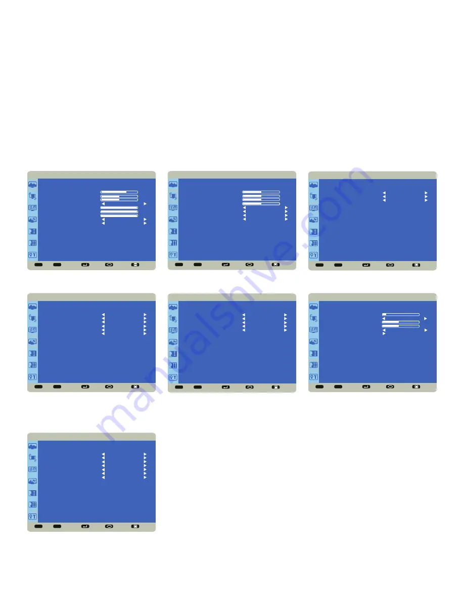
OSD (ON-SCREEN DISPLAY) MENU SYSTEM

The OSD provides the user the ability to control the monitor display. 

To access the OSD, press the 

Menu

 button on the remote or the keypad located on the right-hand side of the monitor.

Use the up and down arrows on the remote or keypad to scroll through the menu options and press 

OK

 to enter the 

highlighted menu. Use the up and down arrows and 

OK

 button to select the item you would like to adjust. Left and right 

arrow buttons are used to make adjustments. 

When your adjustments are complete, press the 

Back

 button to go to a different menu or press the 

Menu

 button to exit 

the OSD menu entirely.

The following pages describe each of the OSD menus in detail.

Sel

Adjust

Enter

Back

Quit

< >

< <

PICTURE

BRIGHTNESS

CONTRAST

SHARPNESS

COLOR TEMPERATURE

COLOR CONTROL

PICTURE MODE

PICTURE RESET

NATIVE

STANDARD

NO

70

50

50

100

100

100

RED

GREEN

BLUE


Sel

Adjust

Enter

Back

Quit

< >

< <

SCREEN

H POSITION

V POSITION

CLOCK

CLOCK PHASE

BLANK

DIMMING

ASPECT RATIO

SCREEN RESET

50

50

50

50

OFF

70

WIDE

NO


Sel

Adjust

Enter

Back

Quit

< >

< <

AUDIO

SPEAKER

AUDIO SOURCE

AUDIO RESET

INTERNAL

MONDOPAD

NO

Sel

Adjust

Enter

Back

Quit

< >

< <

PIP

PIP MODE

PIP INPUT

PIP POSITION

PIP SWAP

PIP SIZE

PIP AUDIO

PIP RESET


NO

VGA

TOP-RIGHT

NO

SMALL

MAIN

NO


Sel

Adjust

Enter

Back

Quit

< >

< <

CONFIGURATION 1

LANGUAGE

AUTO SOURCE

USB HUB SWITCH

CONFIGURATION RESET

FACTORY RESET

ENGLISH

NO

AUTO

NO

NO


Sel

Adjust

Enter

Back

Quit

< >

< <

CONFIGURATION 2

OSD TURN OFF

FREEZE

OSD H POSITION

OSD V POSITION

OSD ROTATION

MONITOR INFORMATION

10

50

50

OFF

PORTRAIT

Sel

Adjust

Enter

Back

Quit

< >

< <

ADVANCED OPTION

GAMMA SELECTION

OVER SCAN

IR CONTROL

KEYPAD CONTROL

DDC/CI

LIGHT SENSOR

ADVANCED OPTION RESET

MODE1

ON

NORMAL

LOCK

ON

OFF

NO

Summary of Contents for INF6500E

Page 1: ...USER GUIDE INF6500E 009 1653 00...

Page 2: ...Connecting AC power 12 External PC touchscreen control setup 12 Turning the Monitor On Off 12 Using the Remote 13 Using the Keypad 15 OSD On Screen Display Menu System 16 Picture 17 Screen 18 Audio 1...

Page 3: ...erated in a commercial environment This equipment generates uses and can radiate radio frequency energy and if not installed and used in accordance with the instruction manual may cause harmful interf...

Page 4: ...ices including amplifiers that produce heat Do not place the monitor in direct sunlight humid greasy or dusty places or in places where the monitor may come into contact with rain smoke or steam The m...

Page 5: ...l and stand mounting hardware that meet this product s specifications and follow the manufacturer installation instructions The warranty does not cover any damage caused by use of improperly rated mou...

Page 6: ...Page 6 1 InFocus 8 12 UL1678...

Page 7: ...Source USB cable Remote control batteries not included Documentation 1920 x 1080 monitor Power cord varies per country For additional accessory options such as stands feet carts and wall mounts see th...

Page 8: ...he mounting means should be strong enough to bear the weight of the monitor Do not install the monitor in places subject to mechanical vibration Do not place the monitor on an unstable surface which c...

Page 9: ...nd audio source devices can be connected to the connection panels on the front back and side of the monitor Available jacks include HDMI In 5 PC In 1 Composite Video 1 Component RCA 1 RS232 1 Audio In...

Page 10: ...ve to this USB Type A 2 0 connector Used for firmware upgrades SOURCE USB Connect a USB thumb drive to this USB Type A 2 0 connector Used for firmware upgrades TOUCH USB Connect a USB cable from the d...

Page 11: ...an HDMI external device such as a VCR or DVD player VIDEO Connect a composite video cable from the monitor to an external device such as a VCR or DVD player D RS232 Connect to an RS232 control device...

Page 12: ...e External PC touchscreen control setup 1 Connect an external computer to the monitor using a DVI HDMI or VGA cable 2 Connect one end of the USB A USB A cable to the USB A jack on source computer conn...

Page 13: ...range of optimum operation is about 26 8m and within a horizontal and vertical angle of 30 degrees 30 30 CAUTION When disposing of the batteries be sure to do so in an environmentally proper manner If...

Page 14: ...n a secondary source has not been selected PIP SWAP PiP Swap Switches the position of the main and secondary sources PIP POSITION PiP Position Moves the PiP window position from corner to corner upper...

Page 15: ...ressed for more than four seconds the monitor goes into standby Input button Turns the Source menu on allowing the user to change sources Saves changes selections if the OSD menu is on button Moves th...

Page 16: ...NTRAST SHARPNESS COLOR TEMPERATURE COLOR CONTROL PICTURE MODE PICTURE RESET NATIVE STANDARD NO 70 50 50 100 100 100 RED GREEN BLUE Sel Adjust Enter Back Quit SCREEN H POSITION V POSITION CLOCK CLOCK P...

Page 17: ...white in the image Range 0 100 Default 50 Sharpness changes the clarity of the edges of a video image Range 0 100 Default 50 Color Temperature changes the intensity of the colors Options include Nati...

Page 18: ...Clock adjusts the width of the image For VGA input only Range 0 100 Default 50 Clock Phase adjusts the focus clarity and stability of the image For VGA input only Range 0 100 Blank When enabled a blan...

Page 19: ...include Internal both internal and external speakers operate and External only external speakers operate Default Internal Audio Source selects the audio input source Options include HDMI 1 HDMI 2 HDM...

Page 20: ...include Yes and No PIP Size changes the size of the PiP window used in the Corner to Corner configuration Options include Small default Middle and Large PIP Audio switches the audio source from the ma...

Page 21: ...tay on the last selected source regardless of whether an active source is detected or not Options Yes and No default USB Hub Switch allows the user to use the touch functions from an input source excl...

Page 22: ...When enabled freezes the image which is currently displayed Options On and Off default OSD H Position adjusts the horizontal position of the OSD menu Range 0 100 Default 50 OSD V Position adjusts the...

Page 23: ...default IR Control disables and enables the IR sensor on the monitor Options include Normal default IR is enabled and Lock IR is disabled Keypad Control disables and enables the keypad on the right ha...

Page 24: ...y that connections between the source and the monitor have been made correctly Verify that the cables are in good condition No touchpad activity with external computer Verify that the USB B to USB typ...

Page 25: ...uted An HDMI 1 3 or higher source and source device is required to hear audio via the HDMI cable LED Indicators FRONT LED near IR sensor SOLUTION Orange The monitor is asleep Press the Power button on...

Page 26: ...for which the refund is provided must be returned to InFocus and becomes InFocus s property This is your exclusive remedy for defective products Limited Warranty Periods vary depending on your produc...

Page 27: ...contamination improper or inadequate maintenance cleaning or calibration liquid contact unusual physical or electrical stress and or power surges virus infection fire earthquake disaster lightning or...

Page 28: ...rm arising out of the agreement to purchase the Product is governed by the laws of the State of Oregon U S A Mandatory Arbitration Any action regardless of form arising out of the agreement to purchas...

Page 29: ...on in the provided shipping material Failure to return the defective part may result in InFocus charging you for the replacement With a Customer Self Repair InFocus will pay all shipping and part retu...

Page 30: ...ications installed on the hardware may not be compatible or work with the hardware as a result of the system software update You will be responsible for reinstalling all other software programs data a...

Page 31: ...Page 31 INF6500e User Guide 1 98 5 4 1 2 1 M8 12 UL1678...

Page 32: ...Page 32 JTouch 65 I O port Source A B D C...

Page 33: ...3 INF6500e User Guide A HDMI 5 HDMI PC USB PC B USB A SOURCE USB U USB Type A USB2 0 SOURCE USB U USB Type A USB2 0 TOUCH USB USB USB Monitor B C COMPONENT DVD HDTV YPbpr VGA RGB HDMI1 4 HDMI VIDEO VC...

Page 34: ...Page 34 D RS232 PC AUDIO LINE IN PC AUDIO IN1 iPod AUDIO IN2 DVD AUDIO OUT OSD OSD OSD OSD OSD OSD...

Reviews: