


5
Powered Subwoofer
HPS-250
DISASSEMBLY PROCEDURES
AmplifierRemoval
1.
Lay the subwoofer on its side on a padded surface,
amplifier facing upwards.
2.
Locate and remove the (2) Allen head screws (#2) at
the bottom of the plastic cover with a 3/32” wrench.
3.
Slide the amplifier straight down until it clears the slotted
brackets (#4) & (#5); pull away from the cabinet and
expose for servicing without further disconnection.
4.
To remove individual boards if desired, remove Philips
screws and all relevant molex or other connectors.
5.
Wires threading through the cabinet, glued in place,
should be left intact under all circumstances.
WooferRemoval
1.
DO NOT ATTEMPT TO PRY THE GRILLE (#10) OUT
OF ITS RECESS.
2.
Lay the subwoofer on its side on a padded surface.
3.
Remove the (4) rubber foot plugs (#15).
4.
Remove the (4) 1” foot screws (#16), remove all four
feet.
5.
Remove all (8) 2” expose bottom panel screws (#13).
6.
Pull the bottom panel (#12) out of the cabinet - one way
to accomplish this is to partially screw one of the 2”
screws back into a threaded “foot” hole and pull on the
screw. Lift the bottom panel & woofer (#9) out of the
cabinet.
7.
Unplug both woofer terminals; remove all (8) 3/4” screws
(#11).
Bias Test
1.
Remove and expose amplifier assembly by following
instructions above. All connectors must remain intact.
2.
Locate and disconnect the CD+ connector on the main
board; insert a DCAmmeter set to a low range between
the connectors.
3.
Locate and adjust R13 and R28 potentiometers on the
main board near the connector to maximum CCW.
4.
Connect power cord, turn on power switch; verify initial
DCcurrent is less than 1.5mA.
5.
Adjust R28 CW slowly until meter reads 5 mA.
6.
Now adjust R13 CW slowly until meter reads 10 mA.
7.
Turn power OFF; disconnect Ammeter and re-connect
CD+ terminal.
Audio Test
1.
Remove the woofer by following instructions above;
replace with a 20 ohm 100 watt resistive load.
2.
Connect a voltmeter (Wavetek DM25XT or similar) and
oscilloscope to the amplifier output terminals, plus the
load.
3.
Adjust the Gain control to minimum. Frequency should
be set to maximum. (Pahse is irrelevant); there is no
input signal for this test.
4.
Turn on the unit; Observe voltage on oscilloscope and
rotate controls; ACnoise should be less than 8 mV.
5.
Adjust the Gain control to minimum; Frequency should
be set to maximum. (Phase is irrelevant) Connect a
signal generator to the Left Low Level (RCA) input; only
one cable is necessary; set the generator to 60Hz,
800mV.
TEST PROCEDURE 1
WHEN SERVICING THIS AMPLIFIER:
1.
Do not touch the metal frame of the woofer (if removed from the cabinet) when driving the amplifier at high
power levels. In the unlikely event that the output devices in the amplifier fail and present an open circuit during
their operation, AND the driver voice coil was to come in contact with the motor assembly, hazardous voltage could
be present at the woofer frame.
2.
When 120/230v-based test equipment is connected to the amplifier in any way, use of a 1000W isolation
transformer (Stancor model GIS-1000 or similar) on the subwoofer is necessary for safety; in addition, an isolator
plug, (a three-to-one pin adapter sometimes called a “cheater plug”) should be used on the power cord plug of the
test equipment being used.
Summary of Contents for HPS-250
Page 4: ...3 Powered Subwoofer HPS 250 HPS 250 BLOCK DIAGRAM ...
Page 12: ...1 1 Powered Subwoofer HPS 250 HPS 250 PACKAGING EXPLODED VIEW ...
Page 13: ...1 2 Powered Subwoofer HPS 250 INTEGRATED CIRCUIT DIAGRAMS ...
Page 14: ...1 3 Powered Subwoofer HPS 250 PRINTED CIRCUIT BOARD POWER SUPPLY ...
Page 15: ...1 4 Powered Subwoofer HPS 250 PRINTED CIRCUIT BOARD MAIN BOARD ...
Page 16: ...1 5 Powered Subwoofer HPS 250 PCBs AC POWER SHIELD LED H I SHIELD ...
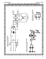
Page 17: ...1 6 Powered Subwoofer HPS 250 LINE FILTER LOW LEVEL INPUT SHIELD LED BOARD SCHEMATICS ...
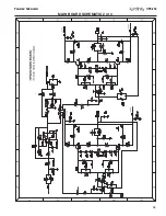
Page 18: ...1 7 Powered Subwoofer HPS 250 MAIN BOARD SCHEMATIC 1 of 3 ...
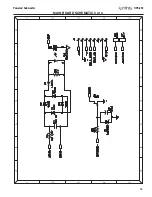
Page 19: ...1 8 Powered Subwoofer HPS 250 MAIN BOARD SCHEMATIC 2 of 3 ...
Page 20: ...1 9 Powered Subwoofer HPS 250 MAIN BOARD SCHEMATIC 3 of 3 ...
Page 21: ...2 0 Powered Subwoofer HPS 250 POWER SUPPLY SCHEMATIC 1 of 2 ...
Page 22: ...2 1 Powered Subwoofer HPS 250 POWER SUPPLY SCHEMATIC 2 of 2 ...
Page 23: ...2 2 Powered Subwoofer HPS 250 HIGH LEVEL INPUT SCHEMATIC ...


