


TC1784
Micro Link Interface (MLI)
User´s Manual
22-68
V1.1, 2011-05
MLI, V2.0
22.2.7
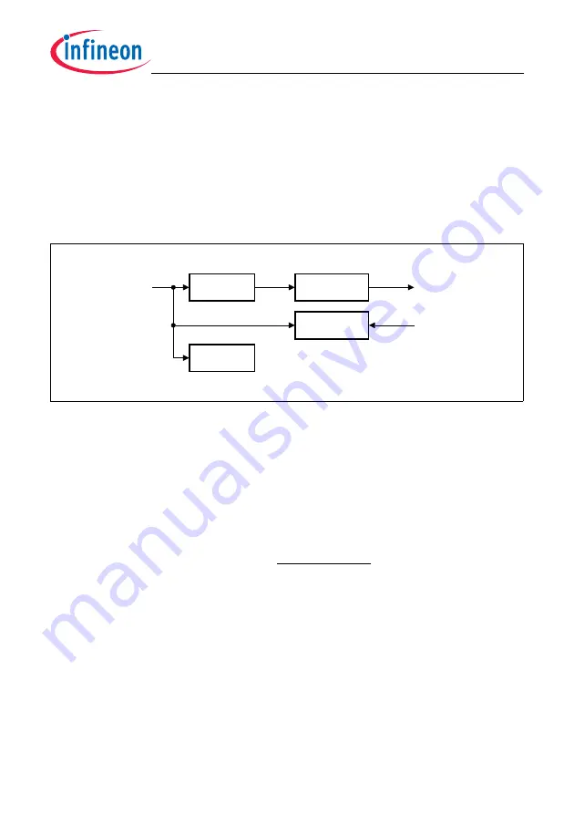
Baud Rate Generation
The MLI transmitter baud rate is given by
f
MLI
/2. The MLI shift clock output signal TCLK
of the transmitter toggles with each clock cycle of
f
MLI
in order to obtain a 50% duty cycle
(the 50% duty cycle can vary up to one clock cycle of
f
SYS
in fractional divider mode). The
MLI receiver automatically adapts to the incoming receive shift clock signal RCLK. The
received baud rate is determined by the connected transmitter and has no direct relation
to
f
SYS
except that it should not exceed
f
SYS
.
The frequency
f
MLI
is generated by the fractional divider FDIV.
Figure 22-48 MLI Baud Rate Generation
Normal Divider Mode
In normal divider mode (FDR.DM = 01
B
) the fractional divider behaves like a reload
counter (addition of +1) that generates a clock
f
MLI
on the transition from 3FF
H
to 000
H
.
FDR.RESULT represents the counter value and FDR.STEP defines the reload value. In
order to achieve
f
MLI
=
f
SYS
, FDR.STEP must be programmed with 3FF
H
. The output
frequency in normal divider mode is defined according the following equation:
(22.1)
Fractional Divider Mode
If the fractional divider mode is selected (FDR.DM = 10
B
), the clock
f
MLI
is derived from
the input clock f
SYS
by division of a fraction of STEP/1024 for any value of STEP from 0
to 1023. In general, the fractional divider mode allows to program the average clock
frequency with a higher accuracy than in normal divider mode. In fractional divider mode
a clock pulse
f
MLI
is generated depending on the result of the addition
FDR. FDR.STEP. The frequency
f
MLI
corresponds to the overflows over
3FF
H
. Note that in fractional divider mode the clock
f
MLI
can have a maximum period jitter
of one
f
SYS
clock period. This jitter is not accumulated over several cycles and does not
FDIV
MCA06324_mod
f
SYS
f
MLI
Transmitter
Receiver
MLI
Registers
TCLK
RCLK
f
MLI
/2
f
MLI
=
f
SYS
×
1
1024 - FDR.STEP
Summary of Contents for TC1784
Page 1: ...User s Manual V1 1 2011 05 Microcontrollers TC1784 32 Bit Single Chip Microcontroller ...
Page 3: ...User s Manual V1 1 2011 05 Microcontrollers TC1784 32 Bit Single Chip Microcontroller ...
Page 950: ...TC1784 Direct Memory Access Controller DMA User s Manual 11 132 V1 1 2011 05 DMA V3 03 ...
Page 1949: ...TC1784 General Purpose Timer Array GPTA v5 User s Manual 21 297 V1 1 2011 05 GPTA v5 V1 14 ...
Page 2350: ...w w w i n f i n e o n c o m Published by Infineon Technologies AG Doc_Number ...


