


50
50
INS
TALLER
US
ER
MAINTEN
AN
CE TECHNI
CI
AN
3.15 PROGRAMMING THE P.C.B.
Th
e boiler is prepared for possible programming of several operation
parameters. By modifying these parameters as described below, the
boiler can be adapted according to specific needs.
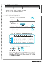
47
To access the program-
ming stage, set the DHW
selector in the “6 o'clock”
position and the heating
selector in the “9 o'clock”
position and press the
“
” and “
”
(Fig. 47)buttons
for about 8 seconds.Once the programming mode has been ac-
cessed, scroll through the five menus (G, P, t, A, F) by pressing the
“
” button for 1 second.
Use the ''D.H.W. regulator'' selector to select the parameter (within
the same sub-menu and when several parameters are available)
and turn the ''C.H. regulator'' selector to alter the value.
Press the "
" button (3) for 1 second to memorise the vari-
ation of the parameters.
Memorisation is represented via "88" on the indicator (Ref. 14 Fig.
14 Fig. 33) for 2 seconds.
Exit the programming mode by waiting for 15 minutes or by press-
ing the “
” and “
” buttons at the same time.
ATTENTION:
if necessary the default values relating
to parameters “S” and “P0
÷
P2” can be
altered by temporarily modifying the type of
gas
(
parameter “G”
)
and by restoring it accord-
ing to the actual operating conditions
(
wait
for approximately 10 seconds between the gas
change and the when it is restored
)
.
Th
e restored values will be those relating to the type of boiler set
in parameters “n” and “F”.
At the end of this operation, anomaly “E62” will appear and com-
plete calibration will be required.
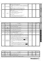
- Menu “G”.
Th
is menu is reserved for the air-gas control settings
and it features two sub-menus (n and S), relating to fan and gas
valve control settings. Every time these parameters are altered,
the complete calibration function must be activated (Par. 3.11).
3.14 FLUE TEST.
To define the value to set in the ”
fl
ue length” “F0” parameter, detect
the parameters during the “
fl
ue test”.
N.B.:
before performing the test, ensure that the
condensate drain trap has been filled correctly and
check that there are no obstructions in the air intake
circuit and
fl
ue exhaust and that the sealed chamber is
perfectly closed and the
fl
ue has already been installed.
Once the test has been carried out properly, note the detected value
in the relevant table, in order to have it available for future checks.
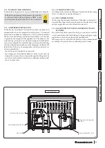
46
To activate this mode, the
boiler must be in “stand-
by” mode, which is visible
w h e n t h e
( ) symbol appears.
N.B.:
if the boiler is connected to the CAR
V2
the “stand-by” func-
tion can only be activated via the remote control panel.
To activate the function, press the buttons “
” and
“ ” simultaneously until function activation, which is displayed
by indicating the fan operation speed (in hundreds of revs) and
ignition of the
fl
ashing “D.H.W.” (
) and “central heating”
(
) symbols.
Th
e appliance remains in this mode for a maximum period of 15
minutes, keeping the fan speed constant.
Th
is function ends once 15 minutes have elapsed, or by discon-
necting supply voltage to the boiler, or by pressing the “ ” button
for approximately 8 seconds.
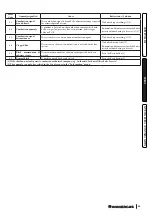
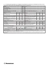
Check the ΔP between the two pressure test outlets (Ref. 13 Fig.
32) according to the values shown in the tables below:
Victrix Zeus 25
Parameter F0
Pressure
0
<
90 Pa
1
90
÷
120 Pa
2
120
÷
150 Pa
Value detected on first check
N.B.:
examinations are carried out by sealing the holes provided
to analyse the
fl
ues, making them pneumatically sealed.
N.B.:
should there be a boiler malfunction, you can carry out a
fl
ue test to check that there are no obstructions in the
fl
ue system.
Different values to those indicated in the previous tables indicate
a
fl
ue system malfunction, especially a
fl
ue system with excessive
load losses or obstructed system.


