


48
48
INS
TALLER
US
ER
MAINTEN
AN
CE TECHNI
CI
AN
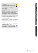
In order to access the complete calibration stage, you must switch
the boiler on, set the DHW selector in the “6 o'clock” position
and the heating selector in the “9 o'clock” position, (Fig. 39) and
press the “
” button for about 8 seconds until the “chimney
sweep” function is activated; then press the “
” button within
3 seconds. If the temperature read from the storage tank during
this phase is below 60 °C, the boiler can be switched on. Follow
the operations described
to start calibration.
If the energy produced in
the central heating circuit
needs to be discharged,
turn the selector to 0 after
the calibration function is
enabled.
•
Nominal heat output:
with the function active, the boiler carries
out the procedures required to calibrate the appliance at the
nominal heat output.
At this stage, the display features
fl
ashing icons: “ ”, “ ”,
“ ” and the operating temperature alternated with the current
operating heat output (99
%
);
40
once the parameters are
detected and stabilised,
the frame of the flame
presence symbol will start
flashing (
) (this
procedure may last a few
minutes), meaning that
the nominal heat output
parameters have been set.
It is only possible to correct the CO
2
(Par. 3.12) value after the
fl
ame presence (
) frame
fl
ashes, or switch to the next
heat output parameter by pressing the “
” button.
•
Intermediate heat output ignition:
once the nominal heat
output calibration is confirmed, the boiler is calibrated with the
intermediate heat output (or ignition heat output).
At this stage, the display features
fl
ashing icons: “ ”, “ ”,
“ ” and the operating temperature alternated with the current
operating heat output (typically 41
%
but variable according to
the boiler model);
41
once the parameters are
detected and stabilised, the
frame of the flame pres-
ence symbol (
)
will start
fl
ashing, mea-
ning that the intermedia-
te heat output parameters
have been set.
It is only possible to correct the CO
2
(Par. 3.12) value after the
fl
ame presence (
) frame
fl
ashes, or switch to the next
heat output parameter by pressing the “
” button.
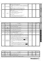
39
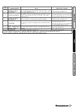
3.10 CALIBRATION TYPE INVOLVING THE
REPLACEMENT OF A COMPONENT.
When performing extraordinary maintenance on the boiler,
involving the replacement of a component, such as the P.C.B. (if
the removable memory is not put into the replacement board) or
components in the air, gas and
fl
ame control circuits, the boiler
will need to be calibrated.
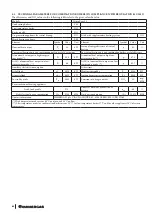
Select the type of calibration to be carried out according to the
table below.
Replaced
component
Type of calibration required
Gas valve
Q
uick calibration
Fan
Q
uick calibration
Burner
Complete calibration with CO
2
check
Ignition/detection electrodes
Complete calibration with CO
2
check
P.C.B.
(New virgin P.C.B. without re-
movable memory recovery)
Restore the parameters as de-
scribed in the paragraph "P.C.B.
programming"
Complete calibration with CO
2
check
P.C.B.
(Recovery of the removable
memory with the boiler param-
eters set from the replaced board)
No calibration required.
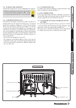
3.11 COMPLETE CALIBRATION FUNCTION.
N.B.:
before carrying out complete calibration, ensure that all
the requirements indicated in Par. 1.23 and 1.24 have been met.
In the event of anomaly “62” or “72” (Par. 2.5) the boiler cancels
any requests by itself.
N.B.:
During the various calibration stages, the CO
2
value can be
checked and possibly corrected as described in (Par.3 12.
The energy produced is dissipated via the heating circuit; al-
ternatively, the energy can be released from the DHW circuit by
opening any hot water tap.
ATTENTION:
in this case the only active temperature
control is the
fl
ow probe that limits the
maximum temperature exiting the boiler at
90
°
C, therefore be careful not to get burned.
-
Th
e calibration procedure involves various stages:
- nominal heat output calibration;
- intermediate heat output ignition calibration;
- minimum heat output calibration;
- calibration self-check.
Each calibration procedure, if carried out without altering the
parameters, lasts 5 minutes at the most, after which it switches
automatically to the next parameter until the calibration process
is complete.


