


20
C
13
1
2
3
4
5
6
16
C
13
15
C
13
5
4
3
1
2
14
20
INS
TALLER
US
ER
MAINTEN
AN
CE TECHNI
CI
AN
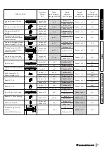
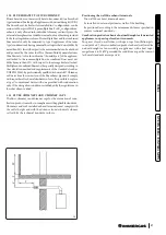
The kit includes:
N° 1 - Gasket (1)
N° 1 - Concentric bend Ø 60/100 (2)
N° 1 - Int./exhaust concentric terminal Ø 60/100 (3)
N° 1 - Internal wall sealing plate (4)
N° 1 - External wall sealing plate (5)
The adaptor kit includes:
N° 1 - Gasket (1)
N° 1 - Adapter Ø 80/125 (2)
The Kit Ø 80/125 includes:
N° 1 - Concentric bend Ø 80/125 at 87° (3)
N° 1 - Concentric intake-exhaust terminal Ø 80/125 (4)
N° 1 - Internal wall sealing plate (5)
N° 1 - External wall sealing plate (6)
The remaining kit components must not be used
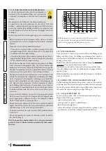
•
Extensions for
Ø
6
0/100 horizontal kit
(
Fig. 15
)
.
Th
e kit with this configuration can be extended up to a max.
horizontal length of 12.9 m including the terminal with grid and
excluding the concentric bend leaving the boiler.
Th
is configura-
tion corresponds to a resistance factor of 100. In this case the
special extensions must be requested.
Immergas also provides a
Ø
60/100 simplified terminal, which in
combination with its extension kits allows you to reach a maxi-
mum extension of 11.9 metres.
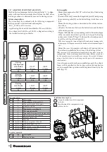
Horizontal intake-exhaust kit
Ø
8
0/125. Kit Assembly
(
Fig. 1
6)
:
to install the kit
Ø
80/125 one must use the
fl
anged adapter kit
in order to install the
fl
ue system
Ø
80/125. Install the
fl
anged
adaptor (2) on the central hole of the boiler, positioning gasket
(1) with the circular projections downwards in contact with the
boiler
fl
ange, and tighten using the screws contained in the kit.
Engage the bend (3) with the male side (smooth) to the end stop
on the adapter (1). Fit the
Ø
80/125 (5) concentric terminal pipe
with the male side (smooth) to the female side of the bend (4)
(with lip seals) up to the end stop; making sure that the internal
(6) and external wall sealing plate (7) have been fitted, this will
ensure sealing and joining of the elements making up the kit.
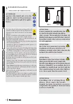
1.14 CONCENTRIC HORIZONTAL KIT INSTALLATION.
•
Type C configuration, sealed chamber and fan assisted.
Th
e position of the terminal (in terms of distances from openings,
overlooking buildings,
fl
oor, etc.) must be in compliance with the
regulations in force.
Th
is terminal is connected directly to the outside of the build-
ing for air intake and
fl
ue gas exhaust.
Th
e horizontal kit can
be installed with the rear, right side, left side or front outlet. For
installation with frontal outlet, one must use the fixing plate and
a concentric bend coupling in order to ensure su
ffi
cient space to
carry out the tests required by law upon commissioning.
•
External grid.
Both the
Ø
60/100 and
Ø
80/125 intake/exhaust terminal, if
properly installed, is pleasant to look at on the outside of the
building. Make sure that the external silicone wall sealing plate
is properly inserted in the wall.
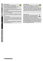
ATTENTION:
for correct functioning of the system
the terminal with grid must be in-
stalled correctly ensuring that, the
"
high
"
indication present on the terminal is respect-
ed on installation.
Horizontal intake-exhaust kit
Ø
6
0/100. Kit Assembly
(
Fig. 14
)
:
install the bend with
fl
ange (2) on the central hole of the boiler,
positioning gasket (1) with the circular projections downwards in
contact with the boiler
fl
ange, and tighten using the screws present
in the kit. Fit the
Ø
60/100 (3) concentric terminal pipe with the
male side (smooth) to the female side of the bend (2) up to the
end stop; making sure that the internal and external wall sealing
plate have been fitted, this will ensure sealing and joining of the
elements making up the kit.


