29
3-3
3-4
1
4
3
2
INS
TALLER
US
ER
MAINTEN
AN
CE TECHNI
CI
AN
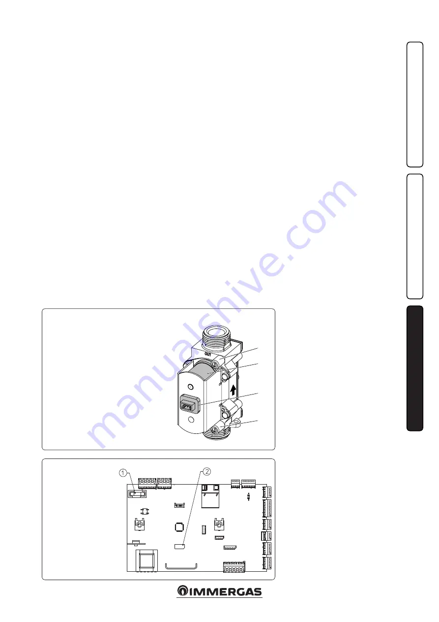
Key:
1 - Fuse 3.15 AF
2 - Removable memory
(A1
9
)
P.C.B.
GAS valve SGV 100 B
&
P
Key:
1 - Gas valve outlet pressure point
2 - Coil
3 - Wiring connector
4 - Gas valve inlet pressure point
Comando Amico Remoto
V2
: the boiler is
prepared for the application of the Comando
Amico Remoto remote control
V2
(CAR
V2
), which
must be connected to clamps 41 and 44 of the
terminal board (located in the boiler control
panel) respecting the polarity and eliminating
jumper X40.
Room thermostat: the boiler is prepared for the
application of the room thermostat (S20), which
must be connected to clamps 40 and 41 of the
terminal board (located in the boiler control
panel) eliminating jumper X40.
The connector X5 is used for the connection to
the relay board.
The connector X6 is for connection to a personal
computer.
The connector X8 is used for software updating
operations.
3.3 REMOVABLE MEMORY
The P.C.B. is equipped with a removable memory
(2 Fig. 3-4), which records all operation param-
eters and system customisations.
Should the P.C.B. be replaced, you can use the
memory of the replaced board again, so it is not
necessary to reconfigure the appliance.
Attention:
replacing the memory must be carried
out after disconnecting all electrical connection
of the P.C.B.
3.4 TROUBLESHOOTING.
N.B.:
maintenance operations must be carried
out by an authorised company (e.g. Authorised
After-Sales Technical Assistance Service).
- Smell of gas. Caused by leakage from gas circuit
pipelines. Check sealing efficiency of gas intake
circuit.
- Repeated ignition blocks. No gas, check the
presence of pressure in the network and that
the gas adduction cock is open.
- Irregular combustion or noisiness. It may be
caused by: a dirty burner, incorrect combustion
parameters, intake-exhaust terminal not cor-
rectly installed. Check the above components.
- Non-optimal ignition of first ignition of the
burner: even if the burner is perfectly calibrat-
ed, first ignition of the burner (after calibration)
can be sub-optimal; the system automatically
regulates ignition until it finds optimal ignition
of the said burner.
- Frequent interventions of the overheating
safety thermostat. It can depend on the lack
of water in the boiler, little water circulation
in the system or blocked pump. Check on the
manometer that the system pressure is within
established limits. Check that the radiator
valves are not closed and also the functionality
of the pump.
- Drain trap clogged. This may be caused by
dirt or combustion products deposited inside.
Check that there are no residues of material
blocking the flow of condensate.
- Heat exchanger clogged. This may be caused by
the drain trap being blocked. Check that there
are no residues of material blocking the flow of
condensate.
- Noise due to air in the system. Check open-
ing of the special air vent valve cap (Part. 24
Fig. 1-29). Make sure the system pressure and
expansion vessel pre-charge values are within
the set limits; The factory-set pressure values of
the expansion vessel must be 1.0 bar, the value
of system pressure must be between 1 and 1.2
bar.
- Noise due to air inside the condensation
module. Use the manual air vent valve (Part.
13 Fig. 1-29) to eliminate any air present in the
condensation module. When the operation has
been performed, close the manual vent valve.
- Poor production of D.H.W. If a drop in per-
formance is detected during supply of D.H.W.,
it is possible that the condensation module
or D.H.W. heat exchanger is clogged. In this
case, contact Immergas After-Sales Assistance
Service that has procedures to clean the module
or D.H.W. heat exchanger.
3.5 CONVERTING THE BOILER TO
OTHER TYPES OF GAS.
If the boiler has to be converted to a different type
of gas to that specified on the data nameplate,
proceed as follows:
The gas conversion operation must be carried
out by an authorised company (e.g. Authorised
Technical After-Sales Service).
To convert to another type of gas the following
operations are required:
- Select, via programming menu “G”, the type of
gas by selecting “nG” for methane gas and “LG”
for LPG gas. (See par. 3.12).
- Carry out complete calibration (see par. 3.8);
during the procedure check and, if necessary,
correct the air - gas ratio.
- Upon completing the conversion, apply the
sticker regarding the modified gas content onto
the data nameplate in the connection box.
These adjustments must be made with reference
to the type of gas used, following that given in
the table (Par. 3.22).
3.6 CHECKS FOLLOWING
CONVERSION TO ANOTHER TYPE
OF GAS.
After having made sure that the conversion is
complete and that the calibration has been suc-
cessful, you must make sure that:
- there is no flame in the combustion chamber
- the burner flame is not too high or low and that
it is stable (does not detach from burner)
- the pressure testers used for calibration are
perfectly closed and there are no leaks from
the gas circuit.
N.B.:
all boiler adjustment operations must be
carried out by a qualified company (e.g. Author-
ised After-Sales Assistance).
Summary of Contents for Victrix Maior 28 TT 1 ErP
Page 1: ...VICTRIX MAIOR 28 35 TT 1 ERP IE Instruction and recommendation booklet 1 038659ENG...
Page 2: ......
Page 49: ...49...
Page 50: ...50...
Page 51: ...51...


