


11
7
INS
TALLER
US
ER
MAINTEN
AN
CE
TECHNI
CI
AN
TECHNI
CAL
D
AT
A
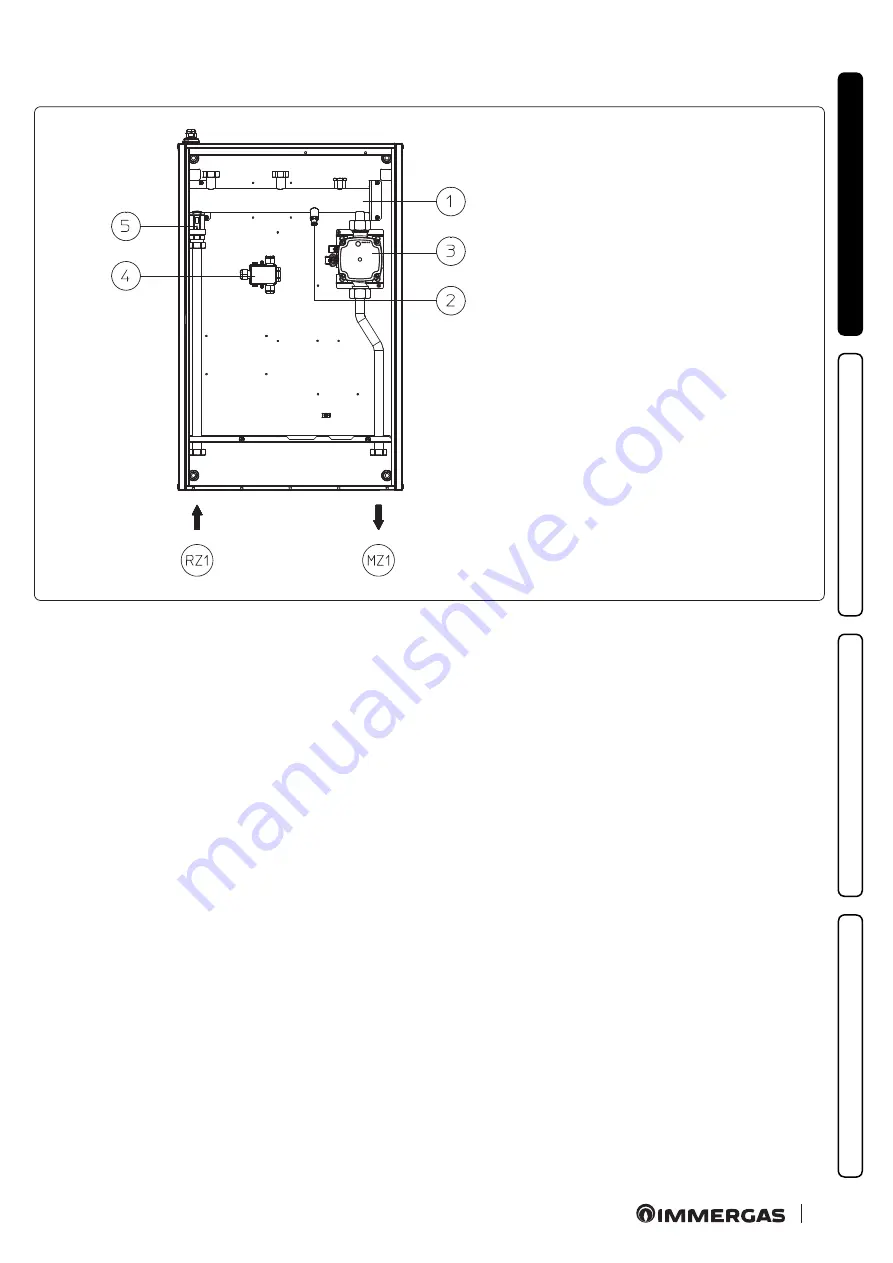
1.8 MAIN COMPONENTS.
Key:
1 - Hydraulic manifold
2 - Drain fitting
3 - Pump
4 - Electrical connection box
5 - “Europa” one-way valve
MZ1 - Direct zone 1 flow
RZ1 - Direct zone 1 return
1.9 SIZING THE SYSTEMS.
The flow temperatures to the various system zones may be reduced
compared to the boiler outlet temperatures, according to the
mixture of the flow and return fluids inside the DIM. In the event
that the DIM is used to feed Low Temperature zones, check that
the design parameters allow you to achieve a maximum surface
temperature of the radiant floor in compliance with standard
UNI EN 1264.
1.10
COMMISSIONING THE DEVICE.
System filling.
Once the device is connected, fill the system via
the boiler filling valve.
Filling is performed at low speed to ensure release of air bubbles
in the water via the boiler and central heating system vents and
of the distribution manifold (if any).
Close radiator vent valves when only water escapes from them.
Close the filling cock when the boiler pressure gauge indicates
approx. 1.2 bar.
N.B.:
during these operations, start the circulation pump by ac-
tuating the main switch on the boiler control panel after having
activated the RT.
1.11
KITS AVAILABLE ON REQUEST.
• System cut-off cock kit (on request). The manifold is designed
for installation of system interception cocks to be placed on
flow and return pipes of the connection assembly. This kit is
particularly useful for maintenance as it allows the DIM to be
drained separately without having to empty the entire system.
The above-mentioned kits are supplied complete with instructions
for assembly and use.