Imesa MCA 1500 Manual Download Page 28

MANCANZA FIAMMA /NO FLAME 


(E140901X) 28 di/of 33 


5.  

ELECTRIC CHECKS 

5.a MCA  

The ignition control unit is connected directly to the valve. The control unit is autonomous in the control of the 
spark ignition, maintenance and verification of the gas presence inside the burner.  

When the machine is in stand-by mode the gas ignition unit is turned off completely and it is not possible to 
apply  any  control  or  reset  operations.  With  the  gas  controller  switched  off  no  alarm 

“NO  FLAME”  can  be 

detected.  

While the machine is in operation and in heating demand, the control unit is turned on by a signal at 230V~ 
supplied by the electronic card IM7. The control unit proceeds to activate the following sequence:  

-  Opening  of  the  valve  by  means  of  excitation  of  the  two  coils.  At  this  juncture  you  hear  a  hissing 
sound coming from the nozzles, caused by the passage of gas;  
- After a second is activated the discharge of the spark plug. At this juncture it is audible a very rapid 
sequence of electrical discharges between the pole "hot" spark plug and ground wire;  
- The burner will light up (except for the problems listed in the previous chapters);  
- The ionization sensor detects the presence of the flame and the consent to the control unit to keep 
lit the valves up to the disappearance of the signal of the heating temperature reached.  

It’s not possible to interact with the control or change the power-up sequence.  

It is not possible to verify if the coils of the valves are electrically supplied from the gas ignition unit.  
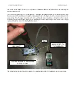
Vice  versa, 

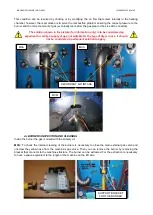
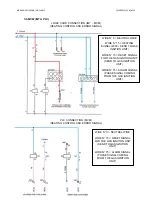
it’s  possible  to  check  the  integrity  of  the  valves  by  controlling  the  impedance  of  the  coils  as 

shown below. The terminals are visible by removing the control unit from the valve body. 


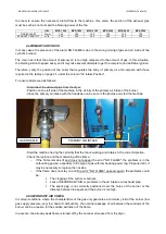
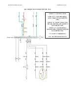
The  ignition  of  the  heating  unit  is  made  by  selecting  a  program  with  a  temperature  higher  than  the  one 
detected  by  the  temperature  probe.  The  signal  at  230V~  comes  directly  from  the  control  board  IM7.  The 
neutral and the earth conductor are not dissected. Following the wiring diagram. 


Summary of Contents for MCA 1500

Page 1: ...IFICA E PULIZIA VENTILATORI E PULIZIA CANNA FUMARIA 11 5 CONTROLLI ELETTRICI 12 5 a MCA 12 5 b MCM IM7 PLC 15 6 SE NON SI RISOLVE IL PROBLEMA STORICO ALLARMI 17 Summary 1 CHECKS THE END USER CAN DO BY...

Page 2: ...i controlli descritti nell apposito capitolo Comunicare al tecnico eventuali problemi di approvvigionamento del gas avvenuti nei giorni precedenti alla comparsa dell allarme 2 INTERVENTO SUL POSTO DA...

Page 3: ...TICA PRESSIONE MINIMA PRESSIONE NOMINALE PRESSIONE MASSIMA GAS METANO 2H G20 PCI 34 02MJ Nm 3 17 00 mBar 20 00 mBar 60 00 mBar GAS METANO 2ELL G25 PCI 29 30MJ Nm 3 18 00 mBar 20 00 mBar 60 00 mBar GAS...

Page 4: ...l ugello va fatta seguendo le indicazioni di seguito elencate Spegnere la macchina completamente Chiudere il rubinetto del gas che alimenta il macchinario Aprire il pannello laterale della macchina in...

Page 5: ...damento acceso risultasse inferiore a quella nominale operare le dovute correzioni agendo su i regolatori di pressione esterni alla macchina e valutare la portata delle condotte del gas dal punto di e...

Page 6: ...possono variare ed essere soggetti a modifica senza preavviso da parte di IMESA SPA U M MCA 1500 MCA 1800 MCA 2100 CONSUMO GAS GAS CONSUMPTION kW 22 24 6 26 m3 h G20 2 9 3 3 3 4 Kg h GPL LPG 2 0 2 2...

Page 7: ...nte un condotto di scarico che deve essere opportunamente dimensionato e realizzato a norma di legge Si definisce pertanto ARIA PRIMARIA l aria aspirata all interno del bruciatore che viene miscelata...

Page 8: ...imane accesa e non compare l errore MANCANZA FIAMMA il problema da ricercare nella carburazione gas aria in particolar modo nella tipologia di gas a basso potere calorifico impiegato ad es Aria Propan...

Page 9: ...re 4 c VERIFICA E PULIZIA BRUCIATORI All interno del bruciatore presente il gas mescolato con l aria primaria MCA Per verificare la pulizia interna dei bruciatori necessario chiudere il rubinetto del...

Page 10: ...lato I bruciatori possono essere lavati sotto acqua corrente e soffiati con aria compressa Durante la pulizia dei bruciatori verificare che non siano presenti rotture nella prossimit delle griglie di...

Page 11: ...l intasamento risulti eccessivo il depressore installato nella macchina provveder a spegnere il sistema di accensione del gas Questa anomalia non viene rilevata dalla scheda elettronica con un errore...

Page 12: ...le una sequenza molto rapida di scariche elettriche tra il polo caldo della candela e il polo di massa Il bruciatore si accendono salvo problemi elencati nei precedenti capitoli Il sensore di ionizzaz...

Page 13: ...A IM7 MCA SEGNALI DI CONTROLLO E ANOMALIA RISCALDAMENTO FILO N 0 NEUTRO FILO N 51 SEGNALE DI RISCALDAMENTO 230V MANDATO ALLA CENTRALINA FILO N 42 RESET CENTRALINA DI ACCENSIONE NEUTRO MANDATO ALLA CEN...

Page 14: ...IAMMA IM7 MCA FILO N 0 NEUTRO FILO N 51 SEGNALE DI RISCALDAMENTO 230V MANDATO ALLA CENTRALINA FILO N 42 RESET CENTRALINA DI ACCENSIONE NEUTRO MANDATO ALLA CENTRALINA FILO N 41 SEGNALE DI ALLARME FASE...

Page 15: ...NOMALIA RISCALDAMENTO FILO N 0 NEUTRO FILO N 15 SEGNALE DI RISCALDAMENTO 230V MANDATO ALLA CENTRALINA FILO N 73 RESET CENTRALINA DI ACCENSIONE NEUTRO MANDATO ALLA CENTRALINA FILO N 75 SEGNALE DI ALLAR...

Page 16: ...6 di of 33 CONNESSIONI SU CENTRALINA DI ACCENSIONE IM7 PLC MCM FILO N 0 NEUTRO FILO N 15 SEGNALE DI RISCALDAMENTO 230V MANDATO ALLA CENTRALINA FILO N 42 RESET CENTRALINA DI ACCENSIONE NEUTRO MANDATO A...

Page 17: ...guente 1 TEMP per passare da un parametro al successivo scelta parametro 2 TEMP per accedere al dato il dato inizia a lampeggiare e pu essere modificato oppure per memorizzare e passare al dato succes...

Page 18: ...ibed in the relevant section Communicate to the technical problems of gas supply that occurred in the days prior to the appearance of the alarm 2 INTERVENTION ON SITE BY THE TECHNICIAN When working on...

Page 19: ...r site The PCI varies depending on the gas supplied to know the PCI gas used to refer to the donor or their institution consult the data of the last gas bill 3 b CHECK OUTLET PRESSURE DYNAMIC PRESSURE...

Page 20: ...e the gas valve shown in the figure Open the screw contained in the pressure tap P out using a screwdriver the screw although completely loose can t get out of his socket Connect your pressure gauge m...

Page 21: ...ary corrections by adjusting the pressure regulators outside the machine and assess the capacity of the gas pipes from the main supply point usually the counter until the machine 3 c CHECKING THE PIPE...

Page 22: ...rding to the consumption flow rate of the machine the diameter of the pipeline has to be suitably dimensioned according to the length of the pipe itself The following table shows for example the secti...

Page 23: ...nition and the maintenance of the flame inside the burner The air is sucked from the room where the ironer is present through the fan blower and it is conveyed to the outside through an exhaust duct w...

Page 24: ...ry air intake of the burner Close the primary air intake with the hands as can be seen in the photos and start the machine Start the machine having the certainty that the fan is working and rotates in...

Page 25: ...y a supply of gas not suitable for the type of dryer in use It should not be considered a permanent solution to apply 4 c BURNERS INSPECTION AND CLEANING Inside the burner the gas is mixed with the pr...

Page 26: ...ent to half the length of the machine on each side The burners can be washed under running water and blown with compressed air While cleaning the burners check that there are no breaks in the vicinity...

Page 27: ...the blockage is too high the depressor installed in the machine will turn off the ignition system of gas This anomaly is not detected by the electronic board with an error visible in the display Ther...

Page 28: ...harge of the spark plug At this juncture it is audible a very rapid sequence of electrical discharges between the pole hot spark plug and ground wire The burner will light up except for the problems l...

Page 29: ...NECTION HEATING CONTROL AND ERROR SIGNAL WIRE N 0 NEUTRAL WIRE WIRE N 51 HEATING SIGNAL 230V SEND TO GAS IGNITION UNIT WIRE N 42 RESET SIGNAL FOR THE GAS IGNITION UNIT SEND TO GAS IGNITION UNIT WIRE N...

Page 30: ...IM7 MCA WIRE N 0 NEUTRAL WIRE WIRE N 51 HEATING SIGNAL 230V SEND TO GAS IGNITION UNIT WIRE N 42 RESET SIGNAL FOR THE GAS IGNITION UNIT SEND TO GAS IGNITION UNIT WIRE N 41 ALARM SIGNAL PHASE SIGNAL COM...

Page 31: ...0 NEUTRAL WIRE WIRE N 15 HEATING SIGNAL 230V SEND TO GAS IGNITION UNIT WIRE N 73 RESET SIGNAL FOR THE GAS IGNITION UNIT SEND TO GAS IGNITION UNIT WIRE N 75 ALARM SIGNAL PHASE SIGNAL COMING FROM THE G...

Page 32: ...MANCANZA FIAMMA NO FLAME E140901X 32 di of 33 CONNECTION TO GAS IGNITION BOX IM7 PLC MCM WIRE N 0 NEUTRAL WIRE WIRE N 15 HEATING SIGNAL 230V SEND TO GAS IGNITION UNIT PR AIR PRESSURE SWITCH...

Page 33: ...tch to the next parameter parameter selection 2 TEMP to access the data the data starts blinking and can be modified or to store and move to the next digit 3 SPEED and SPEED to edit the data WARNING I...

Reviews: