background image

ASSEMBLY

Assembly requires two persons.

Set the treadmill in a cleared area. 

Do not remove the cardboard from the

area shown in drawing 2 below.

Remove all other packing materials. Do not dispose of any packing materials

until assembly is completed.

Treadmill assembly requires the included allen wrench    and your own phillips

screwdriver                      and 9/16” wrench                    .

Note: The underside of the treadmill walking belt is coated with high-performance lubricant. During shipping, a
small amount of lubricant may be transferred to the top of the walking belt or the shipping carton. This is a normal
condition and does not affect treadmill performance. If there is lubricant on top of the walking belt, simply wipe off
the lubricant with a soft cloth and a mild, non-abrasive cleaner.

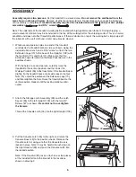
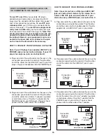
2. Attach the Storage Latch Assembly (33) and the Latch

Spacer (35) to the left Upright (109) with the two 3/4”
Screws (67) as shown. 

Be careful not to overtighten

the Screws.

Thread the Console Latch (55) into the right Upright (109).

109

33

67

55

35

Felt

2

6

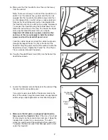
1. While a second person holds one end of the treadmill,

carefully tip the treadmill onto its side as shown. Using the
included allen wrench and a 9/16” wrench, attach the two
Extension Legs (70) to the base of the Uprights (109) with
the four Bolts (71) and Nuts (74). Make sure that the
Extension Legs are turned so the Base Pads (66) are in the
positions shown.

With the help of a second person, carefully raise the
treadmill to the vertical position, and then lower the
Walking Platform (93) to the floor. Note: If the treadmill rocks
slightly, tip the treadmill back onto its side, loosen the four
Nuts (74), adjust the positions of the Extension Legs (70),
and then retighten the Nuts. Raise the treadmill back to the
vertical position. Repeat until the rocking motion is elimi-
nated.

71

109

93

74

70

66

71

74

70

66

1

43

39

55

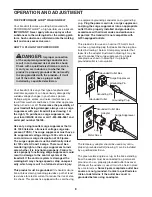
3. Pull the Console Latch (55) to the right, and rotate the

Console Base (43) to the position shown. Release the
Console Latch, making sure that the Console Base is
locked in place. Note: It may be helpful to push down on
the right Handrail (39) and push the Console Latch into
the locked position.

Note: If the Handrail (39) rocks, attach one or two pieces
of the included felt onto the bracket in the locations
shown in drawing 2.

3

Felt

Summary of Contents for Executive 2002

Page 1: ...for reference Visit our website at www imagefitness com new products prizes fitness tips and much more QUESTIONS If you have questions or if there are missing parts we will guar antee complete satisf...

Page 2: ...T 8 HOW TO FOLD AND MOVE THE TREADMILL 21 TROUBLESHOOTING 23 CONDITIONING GUIDELINES 25 ORDERING REPLACEMENT PARTS Back Cover LIMITED WARRANTY Back Cover Note An EXPLODED DRAWING and PART LIST are att...

Page 3: ...surge suppressor could result in damage to the con trol system of the treadmill If the control sys tem is damaged the walking belt may change speed or stop unexpectedly which may result in a fall and...

Page 4: ...d before performing the maintenance and adjustment procedures described in this man ual Never remove the motor hood unless in structed to do so by an authorized service representative Servicing other...

Page 5: ...tomer Service Department toll free at 1 800 999 3756 Monday through Friday 6 a m until 6 p m Mountain Time ex cluding holidays To help us assist you please note the product model number and serial num...

Page 6: ...econd person holds one end of the treadmill carefully tip the treadmill onto its side as shown Using the included allen wrench and a 9 16 wrench attach the two Extension Legs 70 to the base of the Upr...

Page 7: ...l using the cabinet power cord follow the instructions in this step To connect the tread mill using the treadmill power cord see step 4b Important All references to power cords in other sections of th...

Page 8: ...ides a path of least resistance for electric current to reduce the risk of elec tric shock This product is equipped with a cord having an equipment grounding conductor and a grounding plug Plug the po...

Page 9: ...your home stereo portable stereo computer or VCR and play special iFIT com CD and video programs iFIT com CDs and videocassettes are available separately iFIT com CD and video programs automatically c...

Page 10: ...tons Each time a button is pressed the speed setting will change by 0 1 mph if a button is held down the speed setting will change in increments of 0 5 mph To change the speed setting quickly press t...

Page 11: ...asure ment When the desired unit of measurement is selected remove the key and then reinsert it Note For simplicity all instructions in this manual refer to miles To reset the displays press the Stop...

Page 12: ...olumns to the right When only three seconds remain in the first seg ment of the program both the Current Segment column and the column to the right will flash and a tone will sound In addition if the...

Page 13: ...and unplug the power cord from the front of the treadmill HOW TO USE HEART RATE PROGRAMS Follow the steps below to use the heart rate programs Note You must wear the optional chest pulse sen sor see p...

Page 14: ...ngs will move one column to the left The heart rate setting for the second segment will then be shown in the flashing Current Segment column and the speed and or incline of the treadmill will change i...

Page 15: ...5mm Y adapter available at electronics stores Plug the Y adapter into the PHONES jack on your CD player Plug your head phones into the other side of the Y adapter HOW TO CONNECT YOUR PORTABLE STEREO...

Page 16: ...on your stereo HOW TO CONNECT YOUR COMPUTER Note If your computer has a 3 5mm LINE OUT jack see instruction A If your computer has only a PHONES jack see instruction B A Plug one end of the audio cabl...

Page 17: ...to use an iFIT com CD or video program Insert the key into the console See HOW TO TURN ON THE POWER on page 10 Select the iFIT com mode When the key is inserted the manual mode will be selected To use...

Page 18: ...ogram press the Stop button or re move the key and go to step 1 on page 17 Note If the speed or incline of the treadmill does not change when a chirp is heard Make sure that the iFIT com indicator is...

Page 19: ...m will begin and the walking belt will begin to move Hold the handrails step onto the walking belt and begin walking During the program an electronic chirping sound will alert you when the speed and o...

Page 20: ...Speed Min Mile display Press the Speed button to change the unit of measurement IMPORTANT The Calories Fat Calories Heart Rate dis play should be blank If a d appears in the display the console is in...

Page 21: ...st the pin on the storage latch Slowly release the storage latch Make sure that the pin is securely holding the catch plate as shown To protect the floor or carpet from damage place a mat under the tr...

Page 22: ...ith both hands and lower the treadmill to the floor CAUTION To decrease the possi bility of injury bend your legs and keep your back straight Do not drop the treadmill Next pull the console latch to t...

Page 23: ...ring use SOLUTION a Check the circuit breaker see c above b Make sure that the power cord is plugged in If the power cord is plugged in unplug it wait for five minutes and then plug it back in c Remov...

Page 24: ...to turn the left rear roller bolt clockwise 1 2 of a turn if the walking belt has shifted to the right turn the bolt counterclockwise 1 2 of a turn Be careful not to overtighten the walking belt Plug...

Page 25: ...e must be aerobic Aerobic exercise is activity that requires large amounts of oxygen for prolonged periods of time This increases the demand on the heart to pump blood to the muscles and on the lungs...

Page 26: ...illes Stretch With one leg in front of the other reach forward and place your hands against a wall Keep your back leg straight and your back foot flat on the floor Bend your front leg lean forward and...

Page 27: ...NOTES 27...
Page 28: ...Wheel Nut 69 2 Upright Base Endcap 70 2 Extension Leg 71 4 Bolt 72 3 Wheel Bolt Incline Motor Bolt 73 2 Wheel 74 7 Nut 75 1 Wheel Bracket Left 76 1 Plastic Tie 77 1 Tie Block 78 3 Long Belly Pan Scre...

Page 29: ...0 57 58 59 60 67 62 52 66 67 69 54 74 115 66 67 74 74 71 74 73 72 70 71 67 66 74 73 72 71 67 66 70 55 109 40 69 57 58 59 75 67 80 79 76 78 40 78 85 84 83 88 77 82 2 87 78 80 86 5 4 90 7 6 108 91 6 10...

Page 30: ...product or damage to a product caused by or attributable to freight damage abuse mis use improper or abnormal usage or repairs not provided by an ICON authorized service center prod ucts used for comm...

Reviews: