background image


/


Page 76 

Setup Manual 

E.4.2.4 

Domain Name Server 

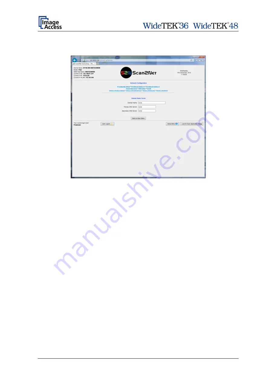
This section defines the parameters for the 

Domain Name Server


Picture 66: Domain Name Server parameters 


Domain Name 

Enter the domain name here. 


Primary DNS Server


Enter the address of the primary DNS server here. 


Secondary DNS Server 

Enter the address of the secondary DNS server here. 


Summary of Contents for WideTEK 48

Page 1: ...Setup Manual ...

Page 2: ...File WT36 48 600_SetupManual_D docx ...

Page 3: ...ibited Scan2Net WideTEK and Bookeye are registered trademarks of Image Access All other trademarks are the property of their respective owners Image Access reserves the right to change the described products the specifications or documents at any time without prior notice For the most recent version always check our web site www imageaccess de or www imageaccess us or the customer service portal a...

Page 4: ...ntively before starting to work with the WideTEK 36 WideTEK 48 By doing so you will avoid operation errors and you can control all functions from the beginning In addition please consider the following points Damages to your unit may have occurred during shipping Please check for damages immediately after delivery of the unit Inform your supplier if damage has occurred Read and ensure that you und...

Page 5: ...to always check for the latest versions of these manuals This manual is divided into the sections A to F Section A contains the safety notes and the safety precautions These safety precautions must be followed carefully to avoid injury to the user while working with the scanner Section B describes the scanner hardware and gives an overview about the scanner s components Section C describes the ass...

Page 6: ...nformation about connectors at the bottom and back side in chapter 3 x C March 2013 Copyright note with updated trademark information The new logos for WideTEK 36C and WideTEK 48C have been introduced New Chapter 5 Monitor Mount Previous chapter B 5 and all following chapters renumbered C1 January 2014 Copyright note updated Technical data updated Setup manuals of WideTEK 36C and WideTEK 48C scann...

Page 7: ...aintenance 20 A 5 1 Touchscreen 20 A 5 2 Surfaces 20 A 6 Repair 20 A 7 Device Location 21 B Transport Box 22 B 1 WideTEK 36 22 B 2 WideTEK 48 24 B 3 Keeping the Transport Box for later use 25 B 4 Scanner Dimensions 26 B 4 1 WideTEK 36 WideTEK 48 without Floor Stand 26 B 4 2 WideTEK 36 WideTEK 48 with Floor Stand 26 B 5 Connectors 27 B 5 1 Main Power Switch 27 B 5 2 USB Connector 27 B 5 3 Back Side...

Page 8: ...e 39 C 4 2 2 Monitor Mount fastening on Base Plate 40 D Setup and Adjustments 42 D 1 White Balance 43 D 2 IP Address 44 D 3 User Settings 45 D 3 1 Change GUI 47 D 3 2 Configure GUI Selection 47 D 3 3 Show Application menu 48 D 3 4 Set Application as default 48 D 4 Time and Date 49 D 5 Testsuite 50 D 6 User Preset 51 D 6 1 Preset Selection Create Preset 52 D 6 2 Preset Selection Configure Preset 53...

Page 9: ...t 66 E 4 1 7 Display 67 E 4 1 8 Guide Plate Middle 68 E 4 1 9 Secure File Erasing 69 E 4 1 10 Kiosk App 70 E 4 1 11 Show Warnings 71 E 4 1 12 Validate Certificates 71 E 4 2 Network Configuration 72 E 4 2 1 IP Configuration Method 72 E 4 2 2 IPv4 Network Interface 0 73 E 4 2 3 IPv4 Network Interface 1 74 E 4 2 4 Domain Name Server 76 E 4 2 5 SMB Settings 77 E 4 2 6 Firewall 78 E 4 2 7 Wireless LAN ...

Page 10: ...erver 100 E 4 7 4 Mail Server 102 E 4 7 5 SMB Configuration 105 E 4 7 6 Web Service Configuration 107 E 4 7 7 USB Device Configuration 111 E 4 7 8 Metadata 113 E 4 7 9 PDF Document 115 E 4 7 10 LDAP Directory Service 117 E 5 Updates Uploads 119 E 5 1 Update Scanner Firmware 119 E 5 2 ICC Profiles 121 E 5 2 1 Scanner Profile 121 E 5 2 2 Printer Profiles 123 E 5 3 Touchscreen Desktop 125 E 5 3 1 Tou...

Page 11: ...139 E 6 3 2 Scan UTT Test Target 141 E 6 3 3 Scan IT8 Test Target 141 E 6 4 Hardware Test Suite 142 E 6 4 1 Network Analyzer 142 E 7 Additional Hardware 145 E 7 1 Wireless LAN 145 E 8 Administrative Settings 146 E 8 1 Wake up Remote Host 146 E 8 2 Change Password 147 E 8 3 Backup Settings 148 E 8 4 Restore Settings 149 E 8 5 Lock Web App 150 E 8 6 Unlock Web App 150 E 8 7 Edit Disclaimer Text 150 ...

Page 12: ...t part 6 F Technical Data WideTEK 36 48 152 F 1 Scanner Specifications 152 F 2 Document Specification 153 F 3 Electrical Specifications 154 F 4 Dimensions and Weight 155 F 4 1 WideTEK 36 155 F 4 2 WideTEK 48 155 F 5 Ambient Conditions 155 ...

Page 13: ... Picture 18 Drawing Detail C 34 Picture 19 Inserting screws with washer 34 Picture 20 Bottom and side components assembled 34 Picture 21 Upper longitudinal foot on vertical leg 35 Picture 22 Upper crossbeam inserted 35 Picture 23 Inserting the rod 36 Picture 24 Floor stand complete 36 Picture 25 Parts of monitor mount 38 Picture 26 Base plate with marking TOP 38 Picture 27 Assembling the base plat...

Page 14: ...uide plate middle 68 Picture 59 List of available erasing methods 69 Picture 60 Kiosk App selection 70 Picture 61 Show Warnings selector 71 Picture 62 Validate Certificates selector 71 Picture 63 IP Configuration Method 72 Picture 64 Settings of IPv4 Network Interface 0 73 Picture 65 Settings of IPv4 Network Interface 1 74 Picture 66 Domain Name Server parameters 76 Picture 67 SMB Settings 77 Pict...

Page 15: ...emplate list for Metadata 113 Picture 98 Metadata parameters 114 Picture 99 Template list for PDF document 115 Picture 100 PDF Document parameters 116 Picture 101 LDAP Directory Service templates 117 Picture 102 LDAP Directory parameters 118 Picture 103 Update Scanner Firmware 119 Picture 104 Scanner Profile 121 Picture 105 Available color spaces 122 Picture 106 ICC Profile information 122 Picture...

Page 16: ... test target 140 Picture 130 UTT test target on glass plate 141 Picture 131 IT8 test target on glass plate 141 Picture 132 Hardware Test Suite start screen 142 Picture 133 Network Analyzer menu items 142 Picture 134 Network Analyzing Parameters 143 Picture 135 Measured Time 144 Picture 136 Packet Statistics values 144 Picture 137 WLAN module successful installed 145 Picture 138 Wake up Remote Host...

Page 17: ... Setup Manual Page 17 ...

Page 18: ... potential hazard A 2 Certification Both scanners fulfill the requirements of the following standards Tested before 06 2014 IEC 60950 1 International Safety Standard for Information Technology Equipment EN 60950 1 Safety for Information Technology Equipment European Standard UL 60950 1 Safety for Information Technology Equipment US standard CAN CSA C22 2 No 60950 1 Safety for Information Technolog...

Page 19: ...ct the Image Access Technical Support 6 Do not put any objects into any scanner housing openings unless specifically instructed to do so by Image Access Technical Support 7 Do not disassemble the scanner If there is a need to disassemble the scanner please contact the Image Access Technical Support 8 Do not use the scanner if it has been physically damaged If this occurs turn the scanner off unplu...

Page 20: ...s are possible A 5 Maintenance Important While cleaning the scanner ensure that no liquids flow into the device housing A 5 1 Touchscreen The touchscreen can be cleaned with a dry microfiber cloth Before cleaning putting the scanner in standby mode is recommended A 5 2 Surfaces Use a soft dampened cloth to clean the housing of the scanner A microfiber cloth is recommended A 6 Repair Note No parts ...

Page 21: ... scanner in an area that has poor air circulation and or that is not ventilated Place the scanner on a flat and solid base The load bearing capacity of the base must correspond to the device weight Choose a location that complies with the temperature and humidity limits Refer to the technical specification Important Before using the scanner in the new environment allow at least one hour for temper...

Page 22: ...hapters give an overview of the content included in the transport box when the scanner is delivered B 1 WideTEK 36 Picture 2 WideTEK 36 transport box The transport box also contains the disassembled floor stand in a separate cardboard box the paper catch basket and cardboard tubes with the accessories Picture 3 Transport box opened 1 Scanner 2 Cardboard box with floor stand optional 3 Paper catch ...

Page 23: ...be lists the content Tube 1 contains Power supply with power cable Foot pedal switch Recovery key with instructions plastic bag Tube 2 contains White Reference Target Patch cable Stitching Target WT36C Z 02 A 2x Paper guides The manuals and a folder with CSTT 2 reference targets lie on top of the scanner After removing the foam inserts lift the wooden frame to get access to the scanner and to the ...

Page 24: ...loor stand optional 4 Paper catch basket 5 Monitor mount optional 6 Reference folder with IT8 sheet and CSTT 2a test target Also contained in the transport box but not visible in the picture Accessory box with Power supply Power cable for power supply with national specification Network cable Foot pedal Manuals Operation manual Setup manual 2x bags with Document Returns and installation manual Whi...

Page 25: ...lements used with the transport box can easily be stored The wooden frame can be folded Most of the foam inserts can be placed between the base plate and the cover plate The wooden frame can be place on top of the cover plate Picture 6 Transport box elements ready to store ...

Page 26: ...7 WideTEK 36 front view The depth and the height of the housing of both scanners are identical B 4 2 WideTEK 36 WideTEK 48 with Floor Stand If the scanner is mounted at the recommended floor stand the resulting height of the complete system is 1070 mm 42 15 inch The combination of floor stand paper catch basket and the document returns at the back side of the scanner makes scanning and the documen...

Page 27: ...er B 5 1 Main Power Switch The main power switch is positioned in the right side cover of the scanner seen from the scanner s front Picture 9 Main power switch B 5 2 USB Connector The USB connector is positioned in the front part of the right side cover of the scanner seen from the scanner s front Picture 10 USB connector ...

Page 28: ...back side B 5 4 Back Side Right On the right rear side of the scanner you will find the connectors for 1 Foot pedal switch 2 Recovery key covered with a plastic cap Picture 12 Connectors at left back side Remove the cap before connecting the Recovery key to the scanner Note The recovery function should only be activated by an administrator Cover the connector again after removing the Recovery key ...

Page 29: ...Floor Stand Box The cardboard box of the floor stand contains a plastic bag with all screws washers and tools required to assemble the floor stand Picture 13 Floor stand box opened Picture 14 Assembling material 1 Table for monitor 2 Plastic bag with assembly material ...

Page 30: ...ked by a circle and capital letter The red circle in the drawing marks the thread nuts No Qty Description 1 2 Crossbeam 2 1 Vertical leg without threaded bushes 3 2 Crossbeam foot Adjustable feet 5 and Hexagon nuts 10 are pre mounted at the crossbeam feet 4 1 Vertical leg with threaded bushes 5 4 Adjustable foot 6 2 Upper longitudinal foot 7 8 Screw ISO 4014 M8x50x22 8 8 Washer DIN 9021 8 4 9 1 Ro...

Page 31: ...imensions of the scanners the floor stands differ in a few details Length of crossbeam WideTEK 36 966 mm WideTEK 48 1271 mm Length of upper longitudinal foot WideTEK 36 WideTEK 48 320 mm Height of vertical leg WideTEK 36 WideTEK 48 830 mm The upper longitudinal feet have a bore hole at each end with a diameter of 24 millimeter ...

Page 32: ... Page 32 Setup Manual C 1 3 List of Assembling Material and Tools A 8x screws ISO 4014 M8x50x22 8x washer DIN 9021 8 4 B Combination wrench size 13 ...

Page 33: ...wo holes with threaded bushes of component 4 marked with red circle will be used to hold the monitor mount They must be positioned to the opposite side Picture 16 Assembly steps Step A Insert a vertical leg 2 or 4 into a crossbeam foot 3 Each crossbeam foot has a cutout for the vertical leg The crossbeam feet are designed symmetrically therefore they fit on the left and right side Step B Insert th...

Page 34: ...the screws with the combination wrench size 13 which comes with the floor stand Note All screws should only be hand tightened at first The components should be a little movable against each other until all parts are assembled Repeat the steps described above with the second crossbeam foot and the second vertical leg Picture 20 shows the floor stand after the previously described assembly steps Pic...

Page 35: ...er longitudinal foot on vertical leg Insert the second crossbeam between the vertical legs Picture 22 Upper crossbeam inserted Assemble the upper crossbeam the upper longitudinal foot and the vertical leg on one side with two ISO 4016 M8x50x22 WS screws and washers at each screw Tighten the screws with the combination wrench size 13 ...

Page 36: ... legs This rod supports the paper output tray It has three positions for adjusting the height of the paper output tray Picture 23 Inserting the rod The floor stand is complete now Picture 24 Floor stand complete Picture 24 shows the floor stand with the inserted rod The threaded bushes red circle are positioned to the outside ...

Page 37: ...ond with the distance of the rubber feet at the bottom side of the scanner Important For safety reasons and because of the weight of the scanner the next steps should always be executed by two persons Place the scanner at the floor stand with the rubber feet into the bore holes There are no additional screws which have to be inserted The scanner is securely held by its own weight ...

Page 38: ... bag A separate list shows the content of the plastic bag C 4 1 Parts of the Monitor Mount Picture 25 Parts of monitor mount The components used to assemble the monitor mount to the floor stand are 1 2x Hexagon head screws M8 x 16 with washer 2 Base plate 3 Allen wrench 2 5 mm 4 Monitor mount Picture 26 Base plate with marking TOP The arrows in Picture 26 show the holes where the screws must be in...

Page 39: ...sitioned outside of the vertical leg In Picture 15 component 4 shows the position marked with a red circle Use two hexagon head screws to fasten the base plate at the vertical leg Picture 27 Assembling the base plate to the vertical leg Assemble the base plate with the hexagon head screws and the washers which come with the Monitor Mount Picture 28 Base plate fastened with hexagon head screws Fast...

Page 40: ...on Base Plate Slide the monitor mount at first on the upper side of the base plate Picture 29 First step monitor mount on base plate Then slide the lower side of the monitor mount over the base plate Picture 30 Final position of monitor mount at base plate ...

Page 41: ...the bottom side of the monitor mount Picture 31 Fixing the monitor mount Use the Allen wrench 2 5 mm to fasten the screws The monitor mount can easily be moved to a position which matches with the operator s needs Picture 32 Floor stand with monitor mount Always mount the monitor to the holding plate with four screws ...

Page 42: ...trol screen Please note The screenshots are taken from a WideTEK 36C but they represent also the scanner versions WideTEK 36 WideTEK 48 The screen will change and shows the first screen of the setup menus The head line shows four of the six available setup menus The small arrow in the menu User Settings indicates that the head line can be scrolled to show also the other menu items Picture 34 Setup...

Page 43: ...arget for optimal calibration Place the reference target WT36A WA 01 A as shown The reference target is delivered with the scanner Touch the Calibrate button During the calibration sequence the reference target will be transported forward and reverse The calibration sequence will take approximately 15 seconds At the end of the calibration sequence the results will be displayed on the touchscreen a...

Page 44: ...igit and press the button Digits will always be deleted from right to left The keys arrow left and arrow right beside the 0 move the cursor in the line Touch Ok button to complete the entry Set network settings Saves the new or modified values when pressed Reset to Factory Resets all network parameters to factory default settings Reset network settings Resets all network parameters to previously d...

Page 45: ...the desired language completes the selection Please note The language of the setup menu mostly remains in English The changing of the language will be activated after touching the Home button Default Returns all scanner settings to default values Change GUI Opens a menu window which shows the predefined settings presets and allows selecting one of these Chapter D 3 1 provides more details Configur...

Page 46: ...e scanner switches to standby mode Click at the selection arrow and select the value from the list It is recommended to restart the scanner after changing the standby settings Volume Click at the selection arrow to set the volume for audio signals Show Application menu To show the application menu when starting the scanner click at the checkbox A little checkmark in the checkbox indicates when the...

Page 47: ...with the presets After selecting one of the presets the scanner starts in Job Mode with the selected preset To return to the previous screen without selecting any preset touch the Back button D 3 2 Configure GUI Selection Picture 39 Presets selection screen All presets are displayed The checkbox in front of each entry defines whether the respective preset is displayed in the Change GUI screen Afte...

Page 48: ... will not be displayed when the scanner starts Application menu will be displayed when the scanner starts D 3 4 Set Application as default To switch directly to the selected application when starting the scanner activate this setting Tap the checkbox in front of Set Application as default Application will not be used as standard when the scanner starts Application will be used as standard when the...

Page 49: ...will always be deleted from right to left Use the numeric keypad in order to enter digits Selecting the time zone By changing the time zone the time that appears on the touchscreen is quickly adapted to the location of the scanner Touch the selecting arrow A list with the available values opens Tap at the desired time zone The zone will be set and the list closes Store time and date Saves the modi...

Page 50: ...est function EMV test function means that the scanner scans permanently without any additional operator action Starting the EMV test Insert an appropriate document for example the CSTT 1 test target which comes with the scanner Push the EMV Test button The document will be transported through the scanner and scanned After a defined length the transport stops and the document will be transported in...

Page 51: ...d Easy Contains only the basic elements of the kiosk application This preset allows modifying only a few parameters Expert Contains all elements of the kiosk application and allows control of all scanner parameters GUI Selection The applications GUI contain individual elements e g logos and control elements which allow adapting the touchscreen to specific needs Applications can be created by syste...

Page 52: ...reset Picture 43 Keyboard on the touchscreen Shifts the keyboard between upper case and lower case characters Deletes the character left of the cursor 123 abc Shifts the keyboard between numeric and letter layout All special characters remain at the same position or Moves the cursor while typing in the input field Apply Saves the new preset Cancel Returns to the former screen ...

Page 53: ...k application shows the message Configure GUI D 6 2 1 Activating a function in the menus Select a menu from the menu list on top of the touchscreen Touch one of the displayed buttons or controller near the respective title and hold it for at least three seconds Release the button A small additional window opens showing in three lines the title of the selected button or controller the action called...

Page 54: ...itches between button controller or list when the function is displayed on the touchscreen b Displays the function always as a button on the touchscreen Touch Ready to save the selected function Touch Cancel to abort D 6 2 2 Saving the preset functions After selecting the desired controller and buttons return to the setup menu Tap the date and time section 10 times Change to the User Preset screen...

Page 55: ... Delete GUI All applications can be deleted except the pre installed application EasyScan Select the application to be deleted from the list Touch the Delete GUI button The application will be deleted The list of applications will not automatically refresh To refresh the list return to the kiosk application press the Home button and open the setup menu again D 6 5 Back to the Kiosk Application Tap...

Page 56: ...categories of the Scan2Net user interface Launch Scan Application changes to the main screen of the user interface Setup Device changes to the setup menu Starting with the following chapter the basics of the scanner configuration will be described Information shows a list of basic information about the scanner e g serial number the firmware version the IP address and many more Select Setup Device ...

Page 57: ...mation and many more Furthermore it allows setting a few basic parameters Poweruser Password protected level This level allows setting an extended range of system parameters and to execute some adjustments It includes all parameters of the User level Admin Password protected level This level allows setting all system parameters and to configure the scanner in detail Access to the Admin level is li...

Page 58: ...ns below the section titles name the parameters which can be set or modified in the respective section The section Device Information is also available from the User level The sections are sorted according to their frequency of use Parameters often used are found in the upper sections Parameters with lower priority are present in the middle sections The Set and Reset Functions can be found in the ...

Page 59: ... log to a text file with the extension log Back to Log File Menu Returns to the previous menu where the desired log file can be selected If data files can be selected and transferred within a menu the menu contains the button Send File Transfers the selected data file to the scanner e g if a firmware update is executed To install an option a unique key code must be entered The respective menu cont...

Page 60: ...vice Info lists the hardware components and provides information about the settings for printer configuration SMB configuration and many more To find the information click the respective links Picture 48 Device Info E 3 2 Operation Info Operation Info shows the scan counters and provides information about operating times of the scanner and the lamps Picture 49 Operation Info ...

Page 61: ...ems follows the order of the menus as they are displayed E 4 1 1 Language Selection Use the function Language Selector to set the language for the Scan2Net user interface Picture 50 Language selector Click on the selection arrow and the list of available languages opens Click on the desired language The change will be executed immediately All texts and messages will be displayed in the selected la...

Page 62: ...s after scanning Picture 51 File name When defining the default name variables can be used To get a list of the variables click at the link Wildcard characters Picture 52 List of wildcard characters Below the field File Name the defined file name is displayed To show the file name with the defined variables reload the page ...

Page 63: ... on the selection arrow to open the list of available values for the respective standby mode Standby mode Available values Device standby Standby Method Suspend to RAM saves the settings of the running processes to RAM The scanner needs less time for start up after standby Power off finalizes all processes After standby the scanner needs more time for the start up procedure Never disables the powe...

Page 64: ...s are available They can be selected in the touchscreen as well as in the ScanWizard interface Use the function Transport Speed to set the values Picture 54 Transport speeds Click at the selection arrows to display the speeds available for the setting Slow and Normal ...

Page 65: ...e volume Click at the scale to set the volume level or right click with the mouse at the arrow and move it to the desired value To return to the previous screen click the button Back to Main Menu To return to the Login screen Picture 46 click the button Setup Menu Click the button Launch Scan Application to switch directly to the main screen of the integrated S2N user interface ...

Page 66: ...k Start Button Timeout to set delay between pressing the start button and the start of the scan sequence Picture 56 Start Button timeout Click at the selection arrows to display the available settings for the delay Click at the desired value to set the time out period ...

Page 67: ...splay parameters The external monitor optional has a resolution of 1366 x 768 pixels by default To change the resolution click the selection arrow in the line Display Resolution Select the desired resolution from the list Restart the scanner to activate the setting To rotate the image on the monitor click the selection arrow in the line Display Rotation ...

Page 68: ...alte Middle to select the color of the guide plate The settings you make here affect correction algorithms while scanning Picture 58 Guide plate middle To change the setting click the selection arrow in the line Color of the installed guide plate Select Black White or Other ...

Page 69: ...s menu item allows selecting the erasing method for files stored in the scanner memory Picture 59 List of available erasing methods Click on the selection arrow to open the list of erasing methods Select the desired method by clicking on the methods name ...

Page 70: ...tton the scanner starts with the selected application No The touchscreen does not show the selection screen Set Application as default Yes The scanner starts with the application selected in Updates Uploads Java Apps See chapter E 5 4 No At the end of the start sequence the touchscreen shows the kiosk application Use HTML Yes The touchscreen shows the HTML based kiosk application No The JAVA based...

Page 71: ... function Show Warnings to set warning messages on or off in the user interface Picture 61 Show Warnings selector E 4 1 12 Validate Certificates Select Yes to activate the validation of certificates when scanning Picture 62 Validate Certificates selector ...

Page 72: ... corresponding to the network where the scanner will be used After modifying the above named values the connection to the scanner must be restored with the new data DHCP Sets the values for IP address subnet mask and default gateway automatically depending on the existing network where the scanner is installed A DHCP server must be accessible in the network For detailed information ask the network...

Page 73: ...hould be used by the scanner Subnet Mask Enter the value for the subnet mask Default Gateway Enter the value for the gateway In most cases this is the IP address of the scanner After modifying the network parameters click on the Apply button to transfer the new settings to the scanner The scanner is now accessible with its new IP address Note After changing the IP address the connection to the sca...

Page 74: ...e 1 The IP address 10 0 0 50 is pre configured for the communication with the WLAN module Default IP address of the WLAN module 10 0 0 1 IP address Enter the IP address for the Network Interface 1 Subnet Mask Enter the value for the subnet mask Default Gateway Enter the value for the gateway After modifying the network parameters click on the Apply button to transfer the new settings to the scanne...

Page 75: ...teway 192 168 1 50 3 Connect the scanner directly with a PC The network parameters of the PC must allow accessing a network with the address range 192 168 1 x 4 Start the scanner and select the Poweruser setup level 5 Select Base Settings Network Configuration Wireless LAN DHCP See chapter E 4 2 10 6 Set the DHCP client range to 172 16 0 51 172 16 0 251 Click the Apply button 7 Select Base Setting...

Page 76: ...ines the parameters for the Domain Name Server Picture 66 Domain Name Server parameters Domain Name Enter the domain name here Primary DNS Server Enter the address of the primary DNS server here Secondary DNS Server Enter the address of the secondary DNS server here ...

Page 77: ...orkgroup Enter the SMB workgroup in which the scanner is installed WINS Server If a WINS server is used enter the IP address of the server or Server name here Use NTLMv2 Authentication Select either Yes or No SMB Protocol Version Select from the settings offered in the list The recommended operation systems for the protocol version are named in brackets Trust server provided hints for kerberos tic...

Page 78: ...kets allow all No restriction for the use of the protocol allow only for Enter the IP address or the address range in CIDR notation for the devices which are allowed to use the protocol CIDR notation means e g 192 168 0 x 24 or 172 16 x x 16 block all Blocks all communication for the protocol After modifying the values click at the Apply button to transfer the modified settings ...

Page 79: ...nd Click on the selection arrow to open the list Select from the list the desired band for the WLAN communication Country Code Select the country where the scanner is used This setting defines the frequency range which is used for WLAN communication in the respective country After selecting another country code click at the Apply button to refresh the channel number list Channel Number The quantit...

Page 80: ...nterface The WLAN modules differ in the IP address which is available for communication The IP address which can be entered here must fulfil two criteria Only IP addresses for private networks are allowed The IP address of the WLAN module and the IP address range of the network where the scanner should be established must not come in conflict IP Address Enter the IP address of the WLAN module Subn...

Page 81: ...s for IPv4 Network Interface 1 and Wireless LAN LAN Interface fit together Picture 71 Wireless LAN Security The screen shows the parameters for wireless LAN security Encryption None No encryption no security WPA 2 Recommended Encryption according to the WPA 2 standard high security Passphrase Enter a string as passphrase here After modifying the parameters click on the Apply button to transfer the...

Page 82: ...WLAN module for DHCP access Note This menu is displayed only if a WLAN module is installed and if the settings for IPv4 Network Interface 1 and Wireless LAN LAN Interface fit together Picture 72 Wireless LAN DHCP Click in the corresponding fields and enter the start IP address and the end IP address to define the address range that can be used ...

Page 83: ...he Manual Adjustment screen The following description starts with the Time Format screen To set the time correctly for the scanner make the adjustments in the following order Select the time zone See chapter E 4 3 2 Set your local time with the manual adjustment See chapter E 4 3 3 Establish a connection to an NTP server See chapter E 4 3 4 ...

Page 84: ...of the Scan2Net user interface can be displayed in either 12h or 24h format Picture 73 Time Format Click on the selection arrow The differences between 12h and 24h format are shown below Time Format 12h Time Format 24h Display from 00 00 to 11 59 Display from 12 00 to 23 59 ...

Page 85: ...n Time Zone to define the time zone for the internal clock of the scanner Picture 74 Time Zone screen Click on the selection arrow A list opens Select the desired time zone from the list The list will close and the selected setting is effective immediately ...

Page 86: ...to be displayed in the headline of the Scan2Net user interface Picture 75 Manual Adjustment To set a value click on the selection arrow beside the respective value Select from the list The new value will be transferred directly to the system clock and is displayed in the headline of the Scan2Net interface ...

Page 87: ...etting To connect to a NTP server the scanner must have a connection to the internet Ask your network administrator for special information concerning your local network Enter the address of the NTP server in the line NTP server It is a necessary requirement that your local network enables the scanner to connect with the internet ...

Page 88: ...he function Set Volume to set the loudspeakers volume of the scanner Picture 77 Set Volume A screen opens and shows a graphic to symbolize the volume level Click at the scale to set the volume level or right click with the mouse at the arrow and move it while holding the mouse button pressed to the desired value To return to the previous screen click the button Back to Main Menu ...

Page 89: ... of the list to search and upload new sounds to the scanner Picture 79 Upload new sound files Click on the button Search to search the directories of your local PC and or your network for sound files Click on the button Send File to upload the selected file to the scanner After uploading the file will be displayed in the list Click on the trash can icon to delete the file ...

Page 90: ...fy the language of the sound file an identifier can be added to the file name For example en marks sound files in English language or de marks sound files in German language Independent from the language selected for the scanner every sound file can be linked to every event Click on the selection arrow beside the sound file name A list with all available sound files opens Select the desired sound ...

Page 91: ...the list Picture 81 Options List To activate an option a unique key must be entered The key is valid only with one specific scanner and cannot be transferred to another scanner The software keys can be purchased at the Image Access Customer Service Portal Visit the URL portal imageaccess de and enter the data for your scanner to get the available keys Enter the key in the respective line and click...

Page 92: ... Page 92 Setup Manual E 4 6 Certificates This section shows the server certificates information Picture 82 Server Certificate information ...

Page 93: ... Owner Filter All Please note The picture could show more templates than installed at delivery To open the templates just click the respective link Setup Opens the parameters of the template Duplicate Copies the template The copy of the template will be saved with the extension Copy of template name in the list of templates Delete Deletes the selected template from the list Name Privacy and Public...

Page 94: ...used for naming the selected images respectively the ZIP archive file Picture 84 shows a part of the list of variables The arrows mark the variables which should not be used in jobmode Picture 84 Excluded wildcard characters The information contained in the file name is only valid for the last image but not for the images in a ZIP archive This limitation affects the settings in the following chapt...

Page 95: ... Setup Manual Page 95 E 4 7 2 Remote Printer Picture 85 Template list for remote printer The data output Remote Printer sends the images after scanning to a previously defined network printer ...

Page 96: ... the printer Port 9100 with IP Networking only Enter the IP port of the remote printer Default is port 9100 Connection Timeout with IP Networking only Choose the timeout for connecting to the remote printer before the connection is aborted Port 139 with SMB Printer Queue only Enter the IP port of the remote printer Default is port 139 Please note Each change of an entry field is transferred to the...

Page 97: ...re HP Color LaserJet Series HP LaserJet Series Postscript Postscript PJL HP DesignJet Series Native Image Format JPEG TIFF PDF Konica Minolta Bizhub Series PDF PJL Changing the data format will change some of the options in this configuration window Data Compression not with all Data Formats Select the data compression of the data to be sent to the printer Resolution not with Native Image Format S...

Page 98: ...r level allows uploading printer ICC profiles to the scanner Available profiles will be displayed in the list Color Matching not with all printer types Select the color rendering method for the remote printer Perceptual The printer uses the nearest matching colors of its own color space Saturation The printer uses the full range of its color space despite of the color definition of the scanned doc...

Page 99: ...s No Account Name Enter the account name here Use Password Yes No Account Password Enter the password for the accounting here Hold Job Yes No Job Type Public Private Hold Key Enter the hold key here Job ID Enter the ID for the job here Please note Each change to an entry field is transferred to the scanner immediately ...

Page 100: ...etup Manual E 4 7 3 FTP Server Picture 87 Template list for FTP Server The data output FTP Server sends the images after scanning to a previously defined FTP server E 4 7 3 1 Setup Picture 88 FTP Server parameters ...

Page 101: ...ssword not with Anonymous FTP Enter the password for the login at the remote FTP server The password is stored using encryption Upload Path Enter the upload path on the remote FTP server starting with root Click on the icon to browse the directory structure of the remote FTP server Note You must have a valid login for browsing the directory structure File name Enter the desired file name Variables...

Page 102: ... Page 102 Setup Manual E 4 7 4 Mail Server Picture 89 Template list for Mail Server The data output Mail Server sends the images after scanning via e mail ...

Page 103: ...ransfer Server Authentication Set to YES if the mail server requires an authentication Login if Server Authentication is set to Yes Enter the user name for authentication at the outgoing mail server Password Enter the password for authentication at the outgoing mail server The password is stored using encryption Protocol Choose the connection protocol SMTP is the most common protocol Connection Ti...

Page 104: ...qualified e mail address Sender Type in the sender of the e mail Format fully qualified e mail address Mail Subject Type in the e mail subject Optional Variables can be added to the mail subject To learn more about the variables click on the link Wildcard characters Reply To Type in a reply address for answers Optional Format fully qualified e mail address Force disposition notification Request a ...

Page 105: ...nual Page 105 E 4 7 5 SMB Configuration Picture 91 Template list for SMB Configuration The data output SMB sends the images directly to a network directory E 4 7 5 1 Setup Picture 92 SMB Configuration parameters ...

Page 106: ...r name for the login at the Windows workstation file server which you want to connect to The password is stored using encryption SMB Path Enter the upload path on the Windows workstation Start with a double slash for the root directory Click the icon to browse the workstation server list and the directory structure of the Windows workstation file server Note A valid login for browsing the director...

Page 107: ...led Cloud The Cloud is an IT infrastructure where service provider offer via a network computing power or storage space at their servers The data is no longer stored locally on the computer but on a remote system Access to the remote systems is realized by using the internet Picture 93 Template list for Web Service Configuration ...

Page 108: ...ote server outside the local network Proxy Address Specify the IP address of the proxy HTTP Proxy Port Enter the port for HTTP communication HTTPS Proxy Port Enter the Port for HTTPS communication Proxy Authentication Select Yes if an authentication should be used Proxy User Enter here the user name for using the proxy Proxy Password Enter here the Proxy password ...

Page 109: ...vice the next parameters will vary Server URL only with WebDAV and Post Methode Click on the selection arrow and select the protocol Enter the server URL Port only with WebDAV and Post Methode Default with http 80 Default with https 443 The value can vary in dependence of the network structure Login With Post Methode only if Authentication Yes Enter your login for the selected web service Password...

Page 110: ... will be examined by an OCR algorithm and the result will be saved This function is currently in beta stadium Subfolder only with Google Docs Select the subfolder where the images should be stored Web Album only with Google Picasa Select an album in your Google Picasa account where the images should be stored File Name Enter the desired file name Variables can be used to define the file name To le...

Page 111: ...orage devices The output option USB enables direct scanning to a USB Standard A flash memory data storage device Picture 95 Template list for USB Device E 4 7 7 1 Setup Picture 96 USB Device parameters Note An USB device must be connected to one of the USB connector at the front side of the scanner to get list displayed in Picture 96 ...

Page 112: ...is link to test the settings A separate window will open and shows the test results Please note Each change to an entry field is transferred to the scanner immediately E 4 7 7 2 List of suitable USB storage media The criteria in the following list have been defined as a guide line for the storage media that can be connected to the USB connectors USB memory sticks USB hard disks USB hard disks with...

Page 113: ...p Manual Page 113 E 4 7 8 Metadata The metadata contain information about the scanned document The metadata will be included into the file attributes of the file header Picture 97 Template list for Metadata ...

Page 114: ...the scanned document is copyright protected Copyright Information The copyright message can be entered here This message will only be embedded in the scanned document if the copyright marker is set to yes URL of extended Copyright Information An external URL which shows a detailed copyright message Keywords comma separated list A list of comma separated keywords which describe the content of the d...

Page 115: ...E 4 7 9 PDF Document The PDF document format is a universal format which allows protecting the document against manipulation PDF documents can be displayed with all common PDF viewers Picture 99 Template list for PDF document ...

Page 116: ...Picture 100 PDF Document parameters Parameter Description PDF Standard Click at the selection arrow and select the desired PDF standard from the list Security System Click at the selection arrow and the desired security system from the list ...

Page 117: ... Setup Manual Page 117 E 4 7 10 LDAP Directory Service Picture 101 LDAP Directory Service templates ...

Page 118: ... 389 Protocol Version LDAP Version 2 LDAP Version 3 Server Authentication Yes No Bind with Server Authentication Yes Enter the desired value here Password with Server Authentication Yes Enter the password here BaseDN Enter the desired value here Base Click at the selection arrow and select from the list Search String Enter the search string here Please note Each change to an entry field is transfe...

Page 119: ...are updates for every Scan2Net scanner In order to download the appropriate firmware version update for your scanner you must be a registered user Log in to the CSP with your personal login name and password Select Actions S2N Device Updates to download the current firmware version Follow the steps described on the website Download the ZIP archive of the current firmware version to your local PC T...

Page 120: ...rring the firmware file can take a couple of minutes depending on the network performance While the update is running no messages will be displayed on the screen After the firmware is successfully updated the screen displays a summary To finalize the update process the scanner must be rebooted This is done automatically if Post Update Behavior is set to Reboot It Shutdown is selected the scanner p...

Page 121: ...dapts the color space between scanner and image editing software Select Scanner Profile to upload an ICC profile to the scanner Already installed profiles will be displayed in a list Picture 104 Scanner Profile Search Click the button to search the directories of your local PC and or your network for ICC profile files Send File Click the button to load the selected file to the scanner After upload...

Page 122: ... scanner Click the Search button to find an ICC profile for the respective color space Picture 105 Available color spaces To delete the ICC profile click on the Delete symbol To get information about the ICC profile click on the information symbol Picture 106 ICC Profile information ...

Page 123: ... for printers adapt the color space of the scanner to the color space of the printer used with the scanner Select Printer Profiles to upload an ICC printer profile Picture 108 Printer Profiles Search Click the button to search the directories of your local PC and or your network for ICC profile files Send File Click the button to load the selected file to the scanner After uploading the ICC profil...

Page 124: ... ICC profile information Selecting the ICC profile to be used In the S2N user interface of the scanner click on the link Options below the button Copy The Printer Preset window opens Click on Printing Enhancements Select Color Matching ICC Profile The additional line ICC Profile is added to the menu below Color Matching Click on the selection arrow All installed ICC profiles will be listed Select ...

Page 125: ...he desired background color from the list with a mouse click Text color Click on the selection arrow to open the list of available colors Select the desired text color from the list with a mouse click Text size Click on the selection arrow to open the list of available sizes from 50 to 400 Select with a mouse click Edit text screensaver Enter the desired text here Click on Apply to transfer the te...

Page 126: ...d new desktop image Click on the Search button to search the directories of your local PC and or your network for a suitable file Send File Click here to transfer the selected file to the scanner A message signalizes the end of the upload sequence To see the available desktop image in detail click on the preview image in the column Image This shows the image in full size Picture 112 Preview of des...

Page 127: ...splayed when the scanner is in stand by mode Picture 113 Lock screen screensaver list Click in the column Select to select the Lock Screen image To delete a desktop image click on the Delete symbol at the right side of the line Click on Back to Main Menu to return to the previous screen Restart the scanner to activate the changes ...

Page 128: ...st click on the Delete symbol at the right side of the line Apps installed as default cannot be deleted The Delete symbol is not displayed To get information about the Java App click on the information symbol in the line of the Java App Upload new Java App Click on the Search button to search the directories of your local PC and or your network for a Java Application file Click on Send File to tra...

Page 129: ...created through the scan process Picture 116 PDF Cover Sheet The preinstalled cover sheets are displayed in the list To delete a PDF cover sheet from the list click on the Delete symbol Click on the View symbol to open the selected file with your associated PDF viewer software Upload new PDF cover sheet Click on the Search button to search the directories of your local PC and or your network for a...

Page 130: ...re 117 Adjustment main screen The White Balance Adjustments section offers the measurement routines to execute the white balance for the streak compensation and to set the brightness correction Enhanced Adjustments allows fine tuning the transport speed The Camera Box Stitching Adjustments section offers the setup routine for the stitching parameters ...

Page 131: ... document table Place the White Reference Target on the document table as shown in the picture above Click on Next Step to start the White Balance Adjustment sequence After the White Balance Adjustment has finished the results will be displayed in a status screen A positive status is displayed in green Any error will be shown in red followed by some explanatory remarks Note It is recommended to ex...

Page 132: ... mouse at the desired position between weak and strong It is recommended to use the default setting Normal Modify the setting in small steps rescan and check the result Selecting strong can result in reduced quality images E 6 1 3 Delete White Balance Data The white balance data measured with the white balance function will be deleted The screen shows an information Click at Delete White Balance D...

Page 133: ... perform any measurements it only allows setting a correction factor for the brightness The interval of the correction factor is 2 dB Picture 120 Brightness Correction factor list Click on the selection arrow to set the desired correction factor The correction factor will be effective immediately ...

Page 134: ...sport Speed This function allows to increase or to decrease the speed in steps of 1 and 0 1 Click with the mouse at the button to modify the speed The current value is displayed between the buttons Picture 121 Transport speed fine tuning ...

Page 135: ...e used Picture 122 Stitching start screen Place the stitching target as shown at the screen at the document table Click on Next Step to start the stitching measurement sequence The scanner transports the stitching target until it reaches the output sensors After the measurement the screen shows two cutouts WT 36 three cutouts WT48 of the scanned millimeter paper Picture 123 Display of cut outs WT3...

Page 136: ...s in transport direction can be displayed Use the buttons Y and Y below each cutout to shift the right part of the cutout against the left part of the image in vertical direction Use the buttons X and X below each cutout to shift the right part of the cutout against the left part of the image in horizontal direction Use the buttons Stitching 0 to Stitching 3 to check the results at defined horizon...

Page 137: ...will be logged with all data Copy Log The data transfer between scanner and printer will be logged USB Log The data transfer to connected USB devices will be logged Web Log The data transfer to a target in the internet will be logged Kiosk Log1 All activities in conjunction with the kiosk functionality will be logged Billing Log All billing relevant data will be logged Viewer Log2 All viewer activ...

Page 138: ...log file A dialog box opens where the operator can select between saving and opening the log file If the operator selects saving the file will be saved in ASCII format which can be opened with any text editor program The Scanner log file has the most comprehensive content and gives a good overview of the scanner activities E 6 2 2 Stitching Log enabled Select Yes to enable the stitching log functi...

Page 139: ...t and the IT8 test target included with the scanner E 6 3 1 Scan CSTT Test Target Click on the respective button to select the CSTT test target for the scan sequence Picture 127 Available test target The next screen shows the position of the CSTT test target Picture 128 Example for test target position Next Step starts the scan sequence ...

Page 140: ...Picture 129 Request after scanning the test target The file name contains some information about the test target and the scanner The example is taken from a Bookeye scanner CSTT FLAT BE4 SGS V2 00199976fc94 CSTT Test target name FLAT Specifies the selected focus mode Other focus modes available depends on the scanner BE4 SGS V2 Device type Here Bookeye 4 version SGS V2 00199976fc94 Serial number o...

Page 141: ...ate The procedure is the same as described with the CSTT test target The resulting image differs in the name because of the other test target E 6 3 3 Scan IT8 Test Target Click on the respective button to select the IT8 test target for the scan sequence Picture 131 IT8 test target on glass plate The procedure is the same as described with the CSTT test target The resulting image differs in the nam...

Page 142: ...is the network analyzer Picture 132 Hardware Test Suite start screen E 6 4 1 Network Analyzer This menu allows to test the network performance and to view the packet statistics Picture 133 Network Analyzer menu items Select either Perform Speed Test or Packet Statistics ...

Page 143: ...n be accessed from the scanner to test the data transfer speed Packet Count Click on the selection arrow to set the number of transferred packets Perform Now Starts the test sequence Back to Net Test Menu Returns to the network analyzer start screen Back to Test Suite Returns to the Hardware Test Suite start screen Picture 132 Back to Main Menu Returns to the Poweruser level main menu Picture 47 ...

Page 144: ... The fastest transfer time between the scanner and the target address Average The average time for all transferred packets Maximum The maximum transfer time during the test Depending at the transfer time the color of the bar changes E 6 4 1 2 Packet Statistics Packet Statistics Shows the current network packet statistics Picture 136 Packet Statistics values ...

Page 145: ... Wireless LAN Use this function after installing a WLAN module to the scanner or when the installed WLAN module has been replaced Click at Wireless LAN The module will be initialized The screen shows a message Picture 137 WLAN module successful installed ...

Page 146: ...e Host The requirements for using this function In the BIOS of the external PC the function Wake on LAN must be activated It may be necessary to update the BIOS of older PCs for this function to be available The main power of the external PC must be active but the PC can be in Power save mode Enter hardware address Enter the MAC address of the network card of the PC here Wake up remote host at Pow...

Page 147: ...to open the list of log in levels Select the log in level for which the password should be changed New Password Enter the new password Retype New Password Type the new password again Note The system checks the syntax upper and lower case of the password Click on Clear Fields to clear the fields where the password can be entered Click on Apply to send the new password to the scanner The screen retu...

Page 148: ...e directory can be opened but all files therein are password protected and cannot be opened Save Saves the ZIP file with an automatically generated file name The contents of the small window change after saving The buttons in the small window allow opening the ZIP file the directory of the ZIP files or opens the download lists in a separate window Save as Save the ZIP file The desired file name ca...

Page 149: ...ngs Picture 141 Restore setting from ZIP file To find the ZIP archive click on Search and browse the directory structure to find the desired ZIP archive file Click on Send File to upload the file to the scanner After restoring the scanner settings the screen shows a message and reminds the operator to perform a White Balance sequence Picture 142 Message after restoring ...

Page 150: ...word Type the new password again Note The system checks the syntax upper and lower case of the password Clear Fields Clears the fields where the password can be entered Apply Sends the new password to the scanner E 8 6 Unlock Web App This function unlocks the user interface Enter the password that has been used to lock the user interface E 8 7 Edit Disclaimer Text This function allows modifying th...

Page 151: ...C Software Operation will not be saved E 9 2 Reset Factory Defaults This function sets all parameters back to factory settings The settings defined for printer output or the connections defined in SMB configuration or the stored email addresses and other parameters will be erased and replaced by universal entries Click on Reset Factory Defaults to execute the function E 9 3 Reset Scanner Defaults ...

Page 152: ...CCD encapsulated and dust proof 12 bit grayscale internal resolution 36 bit color internal resolution Sensor resolution 67 500 pixels 3 x 22 500 Scan modes 24 bit Color 8 bit indexed color 8 bit grayscale 1 bit Black White enhanced halftone WideTEK 36 Illumination Light source Two linear lamps with 154 white LEDs each high quality optical diffusor integrated Warm up time None Max brightness immedi...

Page 153: ...24 bit color 8 bit indexed color 8 bit grayscale 1 bit Black White enhanced halftone WideTEK 48 Illumination Light Source Two lamps with 204 white LEDs each Warm up Time None Max brightness immediately after switch on Temperature Dependence None UV IR Emission None Lifetime 50 000 h typ F 2 Document Specification WideTEK 36 Document Size 915 mm 36 inch wide up to 500 m 20 000 inch long WideTEK 48 ...

Page 154: ...V AC Efficiency 85 Operating temperature 5 to 40 C 40 to 105 F Operating humidity 20 80 RH non condensing ECO standard CEC level V Scanner Voltage 24 V DC Current Max 5 A WideTEK 36 Power Consumption Sleep 0 5 W Standby 4 8 W Ready to scan 35 W Scanning 55 W WideTEK 48 Power Consumption Sleep 0 5 W Standby 4 8 W Ready to scan 46 W Scanning 86 W ...

Page 155: ...ipping weight 95 kg 209 5 lbs F 4 2 WideTEK 48 Scanner outer dimensions 228 x 1425 x 507 mm H x W x D 9 x 56 1 x 20 inch Scanner outer dimensions incl floor stand 1070 x 1425 x 507 mm H x W x D 42 1 x 56 1 x 20 inch Weight of scanner 53 kg 117 lbs Weight of floor stand incl paper output tray 19 kg 42 lbs 21 kg 46 5 lbs Wooden Transport Box Dimension of transport box 470 x 1600 x 800 mm H x W x D 1...

Reviews: