background image


7.6 CONTRAST 


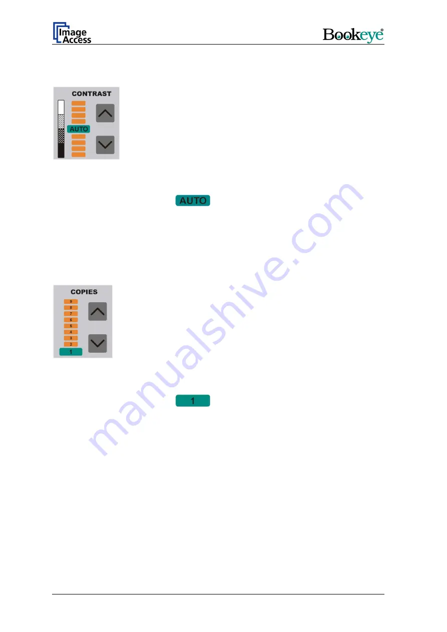
Picture 16: Function field CONTRAST 

The function field CONTRAST sets the contrast value while scanning. 

At the end of the system-test the 

field lights up. 

Moving the LED bar upwards increases the contrast value. Moving the LED bar 
downwards decreases the contrast value. 


7.7 COPIES 


Picture 17: Function field COPIES 

This function field is only active in the copier version of the device. 

At the end of the system-test the 

field lights up. 

The function field COPIES selects the number of copies.  

Page 28 

Operation Manual 

Summary of Contents for Bookeye Color

Page 1: ...Color Operation Manual...

Page 2: ...For your notes File IAC_BE2 SCL R2_eng doc...

Page 3: ...u item has been deleted or moved Additional information concerning firmware update procedure Operation Manual Version D as of July 2005 Valid with device versions R2 and R1 Valid for devices with soft...

Page 4: ...2 6 Cleaning 13 3 Device Overview 14 4 Content on Delivery 15 5 Establishing Connections 16 5 1 Main Power 16 5 2 Connecting the Network Cable 16 5 3 Connecting a Foot Pedal Switch 17 5 4 Possible Di...

Page 5: ...ES 25 7 4 COLOR 27 7 5 BRIGHTNESS 27 7 6 CONTRAST 28 7 7 COPIES 28 8 Set up Mode 29 8 1 Activating the Set up Mode 29 8 2 Checking the current settings 29 8 3 Setting new values 30 8 3 1 Special advic...

Page 6: ...ormat 39 9 2 2 Switching between Portrait Landscape Format 40 9 2 3 Splitting Image 40 9 2 4 Additional Margin Pixel 41 9 2 5 Background Density Binary 41 9 3 Paper User defined Formats 42 9 3 1 User...

Page 7: ...Control Buttons for Output Mode 54 9 6 1 Save 54 9 6 2 Show 55 9 6 3 Print 56 9 6 4 Copy 56 9 6 5 FTP Upload 57 9 6 6 Mail 57 9 7 Turning off the device 58 10 Scanning 59 11 Scan2Net Firmware Update P...

Page 8: ...6 14 2 1 Auto Focus 67 14 2 2 X Adjust 67 14 2 3 Y Adjust 68 14 2 4 Adjust White Balance 68 14 2 5 Leaving the Adjustment Menu 69 15 Technical Data 70 15 1 Electrical Specifications 70 15 2 Dimensions...

Page 9: ...edge 23 Picture 12 Example for document used with FOLDER 24 Picture 13 Function field PAGES 25 Picture 14 Function field COLOR 27 Picture 15 Function field BRIGHTNESS 27 Picture 16 Function field CONT...

Page 10: ...osure and Gamma settings 50 Picture 41 Settings 51 Picture 42 Scan status 52 Picture 43 Color Gain Red 53 Picture 44 Control buttons for output mode 54 Picture 45 Input of directory and file name 54 P...

Page 11: ...to work with the device By doing so you will avoid operation errors and you can control all functions from the beginning In addition please consider the following points Damages to your unit may have...

Page 12: ...the warning sign you find a description of the danger Safety Note Example text 2 2 Connecting to the Power Source Important Before connecting to the power source check the following items The wall out...

Page 13: ...environment allow at least one hour for temperature adaptation 2 4 Replacing Lamps Switch off the device at the main power switch before replacing the lamps As replacement only use original lamps wit...

Page 14: ...ave been identified in the photos here These components are referenced in the operation manual Picture 2 Details on the back side Note Picture 1 and Picture 2 show device version R2 It differs from ve...

Page 15: ...s Over cable is used to connect the BOOKEYE Color scanner directly to a computer via the network card The network cable connects the BOOKEYE Color scanner to the network All parameters which define th...

Page 16: ...wer The power connector and the main power switch are located at the right side of the back of the document bed After the main power switch is turned on the green START LED above the START button ligh...

Page 17: ...mp from turning on To resolve this situation employ one of the two solutions or both if necessary Important For both solutions the following is valid Do not turn off the main power switch and do not d...

Page 18: ...e wait After finishing the self test sequence and during the warm up time of the lamps the display shows Warm up System test ok At the end of the lamp warm up time the display changes to the message D...

Page 19: ...The BOOKEYE Color is now in stand by mode 6 2 1 Special Case Switching off by STOP Key Not Possible If the BOOKEYE Color cannot be switched off due to a system disturbance the device can be powered do...

Page 20: ...RT button starts the scan sequence with the defined parameters During the scan sequence the display shows the current status A brief push of the STOP button interrupts the scan sequence All scanned da...

Page 21: ...ence with format definitions Table 1 indicates the dimensions of the scanned area Lettering Size Lettering Size MAX Maximum scan area LEGAL 215 9 x 355 6 mm A2 420 x 594 mm A4 210 x 297 mm US C 431 8...

Page 22: ...er the whole document If the type FLAT is selected the focus value is measured in a narrow range to the left next to the center line of the document bed The distance to the center line results from th...

Page 23: ...The middle of the book fold must be positioned on the center line Picture 9 Book fold positioned on center line The document must not be positioned at the document bed edge The distance between docum...

Page 24: ...setting PAGES BOTH the left and right half of the document are focused and sent separately Because of the separate focussing for each side it is not necessary to take the documents out of the file Th...

Page 25: ...Output mode SINGLE No page separation Selected document size as one image LEFT Page separation activated Output of the left half of the selected scan area size RIGHT Page separation activated Output o...

Page 26: ...n area white area Example 1 Function field FORMAT A4 Function field PAGES SINGLE Example 2 Function field FORMAT A3 Function field PAGES LEFT Example 3 Function field FORMAT A3 Function field PAGES RI...

Page 27: ...white mode combined with a dithering effect The readability of details in the scan is improved by the dithering B W Scans the document in bi tonal black white mode AUTO No function at this time 7 5 B...

Page 28: ...up Moving the LED bar upwards increases the contrast value Moving the LED bar downwards decreases the contrast value 7 7 COPIES Picture 17 Function field COPIES This function field is only active in t...

Page 29: ...he self test is completed the LEDs light up in the same position which was active when the device was switched off The display now shows the serial number of the BOOKEYE Color in two lines 8 2 Checkin...

Page 30: ...tinuously to change the values fast upwards or downwards 8 3 1 Special advice for the gateway address setting If no gateway is used use the same address as for the IP address setting 8 4 Saving new va...

Page 31: ...User Interface Start your browser Enter the IP address of the scanner The start screen of the integrated user interface opens Picture 18 Start screen Click the button Start Scan Application Operation...

Page 32: ...o three parts The part on the right side shows a menu bar with four menu items Options Paper Camera Settings The part on the left shows the buttons for preview scan and main scan The STOP button switc...

Page 33: ...Options Picture 20 Select options Picture 20 shows all selectable options The option Book Fold Correction must be installed to make it visible below the item Document Processing Operation Manual Page...

Page 34: ...ditional information 9 1 1 1 Options of Book Fold Correction Click on Options to open the Bookfold Options set up window Threshold Defines the threshold for the identification of the hump of the book...

Page 35: ...rees 9 1 4 Image Defines the file format in which the scanned images are stored Available formats are JPEG TIFF PNM Picture 24 Selectable file formats Depending on the selected file format the title o...

Page 36: ...5 JPEG quality in percent Quality Defines the quality of the image in percent TIFF Picture 26 Selection of TIFF compression Compression Defines the type of compressions used for the images Page 36 Ope...

Page 37: ...PNM Raw data of the scanned image No options available for this data format Please note that for all changes the following is valid A new setting or a new value is immediately transferred to the scann...

Page 38: ...ICC Profiles Select Yes to embed ICC profiles to the images ICC profiles are used to set color values for output devices e g printer or plotter Please note that for all changes the following is valid...

Page 39: ...on the selected resolution The surrounding border will be cropped automatically Maximum Scans the maximum scan area of the device User Switches to User defined Formats Refer to chapter 9 3 DIN A2 to...

Page 40: ...or an error message is displayed The response is determined by the browser 9 2 3 Splitting Image Picture 30 Available items for Splitting Image The output of the scanned area can be split Selectable a...

Page 41: ...ty Binary Controls the sensitivity of the automatic document size recognition The higher the selected value the smaller the degree of sensitivity Click on the slider to set the desired value Controls...

Page 42: ...t Picture 31 Setting the user defined format In the middle of the selection window the whole scan area is represented in a schematic form The vertical line marked with 0 corresponds with the vertical...

Page 43: ...fields Bottom Border Height Zero Offset Width This applies to the input of values Maximum Bottom Border Height vertical Maximum Zero Offset Width horizontal If one of the allowed maximum values is ex...

Page 44: ...Java UDF at the menu item Settings refer to chapter 9 5 4 At next click at User defined Formats Picture 33 Preview Scan After a short moment the preview scan is displayed The preview scan shows the co...

Page 45: ...p a frame with the desired size Picture 34 Frame for user defined format After defining the scan area click the Scan Preview Now button or the Scan Now button to start the scan sequence When the scan...

Page 46: ...hich can be changed will vary If a parameter can not be changed the sliders or buttons which belong to this parameter will not be displayed Please note that for all changes the following is valid A ne...

Page 47: ...or modes Available modes are True Color True Color mode with 24 bit color depth Grayscale 8 bit grayscale mode Line Art 1 bit black white bitonal mode Photo 1 bit black white bitonal mode with ditheri...

Page 48: ...ld can be selected in both modes 9 4 1 2 Invert Only available in the modes Line Art and Photo Select Yes to invert the colors in the image 9 4 2 Use CMS Only available if the option Color Management...

Page 49: ...rightness level of the scanned image Use the slider to change the brightness value or enter a numeric value into the field beside the slider Value range from 0 zero to 255 9 4 5 Contrast Sets the cont...

Page 50: ...threshold for black and activates the automatic exposure control These function searches the image for the highest and the lowest pixel value The highest pixel value is defined as white Is the lowest...

Page 51: ...guages are english deutsch and russian If russian is selected all text are displayed in Cyrillic fonts The user interface shows all text in the selected language Please note that for all changes the f...

Page 52: ...tivates an additional window which shows the current status of the scanner 9 5 4 Use Java UDF Click the Yes button to activate Java support while selecting a user defined format UDF stands for User De...

Page 53: ...in Only available in True Color mode Picture 43 Color Gain Red Sets the amplification separately for the red green and blue color channel The amplification can be set in a range from 7 to 7 Operation...

Page 54: ...scanned image The default file name contains date and time as well as a continuous numbering Example Scan 2003 04 22_14 56 24 jpg After scanning the document a window opens in which the directory and...

Page 55: ...eld bar is displayed Use these function fields to save the image refer to chapter 9 6 1 copy the image refer to chapter 9 6 4 send the image via FTP refer to chapter 9 6 5 send the image as e mail att...

Page 56: ...emote printer located in the network The printer must be identified by its IP address To enter the IP address of the printer click on Option below the Copy button A window opens Enter the IP address a...

Page 57: ...Definition of FTP address Click on the button Apply in order to transfer and save the change 9 6 6 Mail Sends a scanned image via e mail To enter the e mail address click on Option below the Mail but...

Page 58: ...Click the Shutdown button Picture 51 Security query after shutdown command After confirming the query the lamps switch off and the display shows the message System Shutdown After the device is switch...

Page 59: ...t the paper format AUTO from Paper Predefined Formats If the option Book Fold Correction is not installed place the document at the document bed edge In all other cases place the document in the middl...

Page 60: ...rnet or if you are connected via a proxy Enter the scanner s IP address in the exception list Additionally it is necessary to force the browser to reload the page content every time directly from the...

Page 61: ...e 6 Please note Pictures show German version of the browser Start your browser and select the menu item as displayed in the picture below The arrow in the screenshots points on the item which has to b...

Page 62: ...The marked menu item shown in the picture above forces the browser to reload the page content each time when it is selected Page 62 Operation Manual...

Page 63: ...Start your browser and select the menu item as displayed in the picture below The arrow points on the item which has to be selected The marked menu item shown in the picture beside forces the browser...

Page 64: ...can2Net Scanner as described in chapter Fehler Verweisquelle konnte nicht gefunden werden 6 Click on the Setup Device button 7 Choose the login level Poweruser 8 Login with user name Poweruser and pas...

Page 65: ...menu items for the setup procedure are accessible in the login level Poweruser 14 1 How to enter the Poweruser level 1 Start your S2N Scan2Net Scanner 2 Start your browser and enter the IP address of...

Page 66: ...rt 2 Press the button Adjustments Picture 54 Poweruser information menu 3 Start in section Focus X Y Adjustments Select the buttons from left to right and follow the steps which are displayed Picture...

Page 67: ...ntrols the button New Values to repeat the measurement Or 6 Click in section Menu Controls the button Back to Adj Menu to return to the adjustments menu see Picture 55 14 2 2 X Adjust This function ad...

Page 68: ...With this function the user can easily adjust the scanner to a white balance which matches its specific needs best 1 Find the section White Balance Adjustment see Picture 55 and click the button Whit...

Page 69: ...ick the Scan Application button to start scanning Notice Generally there is NO reason to open the S2N Scan2Net scanner and work on the hardware However should the device have been opened it is strongl...

Page 70: ...l max 345 W operating 15 2 Scanner Specifications Version N2 and Version R2 Max Scan Area 4800 x 6775 Pixel Max Scan Area 432 x 610 mm Version R1 Max Scan Area 4678 x 6614 Pixel Max Scan Area 594 x 84...

Page 71: ...nsions of the box 1080 x 800 x 780 mm H x W x D Version R2 Dimensions 880 x 1239 x 673 mm H x W x D Weight 33 5 kg Weight ready for shipping 49 5 kg Dimensions of the box 1080 x 800 x 780 mm H x W x D...

Page 72: ...L or SGS or CGS B R or N C 1 or 2 or 3 d or not applicable Serial number All is in conformity with the following European standards and IEC directives EMC directives EN 55022 1998 Class B EN 55024 199...

Reviews: