INSTRUCTIONS FOR USE AND TECHNICAL MANUAL
Vet-Tome
VET-TOME V2000
FOR VETERINARY USE ONLY
Page 1: ...INSTRUCTIONS FOR USE AND TECHNICAL MANUAL Vet Tome VET TOME V2000 FOR VETERINARY USE ONLY...
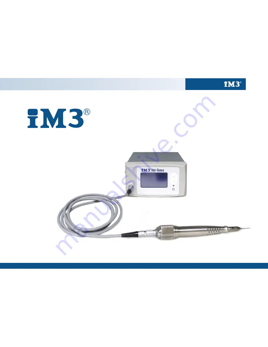
Page 2: ...warranty and any other claims Read all documentation before using the Vet Tome The iM3 Vet Tome is an automated veterinary specific periotome with foot pedal operation that offers precise tooth extra...
Page 3: ...14 15 Handpiece Disassembly 7 Cleaning Handling 16 17 Handpiece Operation 7 Handpiece Tips 17 Tip Installation 8 Sterilization 17 Tip Operation 8 Disposal of Unusable Parts 17 Use Starting 9 Product S...
Page 4: ...If any components have visible defects including dents or scratches that have penetrated the labels or coating discoloration or moisture damage do not use the Vet Tome Contact iM3 or your local distr...
Page 5: ...V Replace only with same type and rating fuse Display Window Hand Piece Connector indicated by grey ring Intensity Value Intensity Icon Increasing Intensity Switch 1 10 Decreasing Intensity Switch 1 1...
Page 6: ...ification repairs or non compliance with instructions invalidates all claims and warranty To avoid overheating the handpiece adhere to duty cycle stated in this manual Do not use any accessories or re...
Page 7: ...rilized with steam Parts must be separated before sterilization Hold the handpiece in one hand Push the exposed portion where the handpiece cable attaches of the solenoid assembly inward towards the h...
Page 8: ...hand that holds the handpiece grasp the release tool either side of the chuck and pull down towards the handpiece as illustrated by the arrows Do not twist or unscrew the chuck when changing tips With...
Page 9: ...er Connect the handpiece cable to the front of the controller Connect the other end of the handpiece cable to the solenoid located in the handpiece Only connect the power cord to a grounded earthed wa...
Page 10: ...dow Hand Piece Connector indicated by grey ring Intensity Value Intensity Icon Increasing Intensity Switch 1 10 Decreasing Intensity Switch 1 10 Hand Piece Standby Switch Intensity Value Intensity Ico...
Page 11: ...Indicator Light Yellow Flashing Attention Required The unit is in an error state See manufacturer s instructions for error conditions Increasing Intensity Switch Increases intensity of the tapping ac...
Page 12: ...the last setting used 1 10 10 being the maximum If the mains power has been turned off the intensity setting will return to 1 Changing Intensity power Settings Power setting should be set to 2 3 for c...
Page 13: ...ely 5mm deep before moving to the next quarter Operate for approximately 10 seconds per quarter do not run the handpiece whilst the tip is being removed from the socket Repeat this technique 3 to 4 ti...
Page 14: ...d thus require replacement iM3 recommends tips should be replaced after 10 uses extractions There is an obvious noise change when inserting the tip into the ligament space vs hitting bone See iM3 webs...
Page 15: ...ble connector to the controller Turn standby switch on If the foot switch is damaged contact iM3 for fault diagnosis and replacement parts Error System Error In the case of an error within the control...
Page 16: ...handpiece tips must be decontaminated and then steam sterilized before use between patients Remove the tip from the handpiece Separate the handpiece and solenoid assembly before decontamination Do no...
Page 17: ...how signs of physical degradation or deformity including colour change do not reuse iM3 recommends replacing hand pieces and tips if this occurs Allow the handpiece and tips to cool at room temperatur...
Page 18: ...ous operation Fuses 2 x T2A 250V Operating Temperature Range 5 to 30 Degrees C Storage Shipping temperature Range 30 to 85 Degrees C Description Catalogue number Vet Tome Tip V1 Standard 5pc V2001 Vet...
Page 19: ...rchase iM3 recommends tips should be used a maximum of 10 times 10 individual teeth before being discarded iM3 accepts no responsibility for damage caused by incorrect handling or by repairs carried o...
Page 20: ...om iM3 Inc 12414 NE 95th St Vancouver WA 98682 USA Ph 1 800 664 6348 Fax 1 360 254 2940 Email info im3usa com iM3 Pty Ltd 21 Chaplin Drive Lane Cove NSW 2066 Australia Ph 61 0 2 9420 5766 Fax 61 0 2 9...