background image

I K U S I

6

21/05/2008

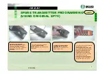
1. Without power, remove the EP70 
EEPROM module from the receiver.

6th Push 

button

6th Push 

button

CHART 3

CHART 3

1. Without power, remove the EP70 EEPROM
module from the receiver.

1. Without power, remove the EP70 EEPROM
module from the receiver.

2. Introduce the EP70 EEPROM module, removed
from the receiver, in the spare transmitter.

2. Introduce the EP70 EEPROM module, removed
from the receiver, in the spare transmitter.

3. Introducing the battery, turn on the key to the ON
position and push and pull the Stop push button.
The LED will light in orange-green, it will make some
blinks in green colour during 15 seconds and it will
get extinguished.

3. Introducing the battery, turn on the key to the ON
position and push and pull the Stop push button.
The LED will light in orange-green, it will make some
blinks in green colour during 15 seconds and it will
get extinguished.

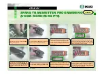
4. Press the 6

th

push button and Start at the same time.

Keep both push buttons pressed while the LED blinks in
red. Once the LED blinks in orange, you can release both
push buttons and the LED will lit in green.

4. Press the 6

th

push button and Start at the same time.

Keep both push buttons pressed while the LED blinks in
red. Once the LED blinks in orange, you can release both
push buttons and the LED will lit in green.

5.Very important thing

. Without stopping the

transmitter, remove the EP70 EEPROM module.

When concluding the process, this removed EP70
EEPROM should be placed in its location in the
receiver.

5.Very important thing

. Without stopping the

transmitter, remove the EP70 EEPROM module.

When concluding the process, this removed EP70
EEPROM should be placed in its location in the
receiver.

6. 

Introduce the blank EP70 EEPROM module

in

the spare transmitter and tighten the two screws.

6. 

Introduce the blank EP70 EEPROM module

in

the spare transmitter and tighten the two screws.

7. 

Press the 6

th

push button for about 5 seconds.

The LED will flash in orange. 

When finishing the

Process, the LED will get extinguished.  The spare
transmitter is already programmed.

7. 

Press the 6

th

push button for about 5 seconds.

The LED will flash in orange. 

When finishing the

Process, the LED will get extinguished.  The spare
transmitter is already programmed.

8. In order to start working, 

push and pull the Stop push

button

. The LED will light an instant in orange-green, it

will make some blinks in green colour during about 15
seconds and it will get extinguished.Pressing Start push
button the system will start to work.

8. In order to start working, 

push and pull the Stop push

button

. The LED will light an instant in orange-green, it

will make some blinks in green colour during about 15
seconds and it will get extinguished.Pressing Start push
button the system will start to work.

SPARE TRANSMITTER PROGRAMMING

(USING RECEIVER EP70)

SPARE TRANSMITTER PROGRAMMING

(USING RECEIVER EP70)

C10

Summary of Contents for TM70 Series

Page 1: ...4 4 2 7 TM70 SERVICE ...

Page 2: ...rane work with the Pendant Control NO The Crane has a problem other than the Remote Control Please contact your Maintenance Service The Crane has a problem other than the Remote Control Please contact your Maintenance Service 9 Change the battery by a charged one NOTE Check that the minimum voltage is 4 8V 9Turn ON the Key in the Remote Control Transmitter 9 Push and Pull the STOP push button 9 Ch...

Page 3: ...ays get activated in the receiver Does the two STOP relays get activated in the receiver YES Does any of the motions fail Does any of the motions fail YES NO 9 Press START push button 9 Press START push button CHART 4 CHART 4 CHART 5 CHART 5 Does the corresponding Relay get activated Does the corresponding Relay get activated P2 P2 YES NO CHART 6 CHART 6 NO P1 P1 ...

Page 4: ...ometimes the Main Contactor turn off on the Crane NO YES END END P1 P1 Does the contact get closed on the output terminals Does the contact get closed on the output terminals P2 P2 CHART 7 CHART 7 YES The Crane has a problem other than the Remote Control Please contact your Maintenance Service The Crane has a problem other than the Remote Control Please contact your Maintenance Service START START...

Page 5: ...r Once placed to fix it tighten the two screws 4 In order to work with the installed EP70 EEPROM module introducing the battery turn on the key to the ON position and push and pull the Stop push button The LED will light an instant in orange green it will make some blinks in green colour during about 15 seconds and it will get extinguished Pressing Start push button the system will start to work a...

Page 6: ...g Without stopping the transmitter remove the EP70 EEPROM module When concluding the process this removed EP70 EEPROM should be placed in its location in the receiver 5 Very important thing Without stopping the transmitter remove the EP70 EEPROM module When concluding the process this removed EP70 EEPROM should be placed in its location in the receiver 6 Introduce the blank EP70 EEPROM module in t...

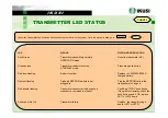
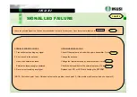
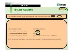
Page 7: ...ng Transmitter cannot start up because a Push pull STOP push button manoeuvre command is present If the problem remains check the push buttons and if OK replace LE71 or LE72 board Solid red or Not Lit Transmitter failure Replace the transmitter logic board LE71 or LE72 LED MEANS RECOMMENDED ACTION Solid Green Transmitter transmitting normally No action transmitter OK OPERATION mode Green pulses Tr...

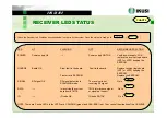
Page 8: ...ving the correct TM70 interference signal Go to data from a TM70 or signal not correct ID ID code OK ID code NOTOK Go to NOTE There are 2 extra LED s in the LR72 card CAN RUN green and CAN ERR red They control the situation of the CAN BUS LED LIT FLASHING OFF RECOMMENDED ACTION POWER Power supply OK Power supply NOTOK Verify power supply If OK replace the receiver logic board LR71 or LR72 keeping ...

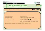
Page 9: ...rings Check that all the wirings are done properly between remote control receiver and the electrical panel and that there is continuity between both sides of the cable NOTE First check point 1 and if this doesn t solve the problem check point 2 and then the point 3 POSSIBLE ERROR SOURCE RECOMMENDED ACTION 1 Receiver relay not closing Replace the LR71 or LR72 card keeping the EEPROM 2 Push button ...

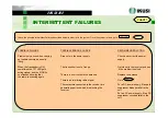
Page 10: ...ng radio signal Go to The contactors connected to the receiver are For a DC power supply fit a spark generating spurious which are blocking the suppressor diode parallel to the receiver coil For an AC power supply fit an RC suppressor circuit parallel to the coil POSSIBLE FAILURE POSSIBLE ERROR SOURCE RECOMMENDED ACTION Problem only arises when carrying Drop outs in the power supply Check and corr...

Page 11: ...or the external antenna Go to 3 Receiver not receiving any signal Replace the LR71 or LR72 card keeping the EEPROM NOTE First check point 1 and if this doesn t solve the problem check point 2 if the problem still is not solved check point 3 POSSIBLE ERROR SOURCE RECOMMENDED ACTION 1 Transmitter not sending any signal Check if the problem is solved with a spare transmitter Go to 2 Short circuit in ...

Page 12: ...h a spare transmitter Go to 3 Receiver not receiving the correct signal Replace the LR71 or LR72 card keeping the EEPROM NOTE First check point 1 and if this doesn t solve the problem check point 2 if the problem still is not solved check point 3 POSSIBLE ERROR SOURCE RECOMMENDED ACTION 1 Frequency interference from other system Go to 2 Transmitter not sending the correct signal Check if the probl...

Page 13: ...e correct ID code Go to 3 Receiver not receiving the correct ID code Replace the LR71 or LR72 card keeping the EEPROM NOTE First check point 1 and if this doesn t solve the problem check point 2 if the problem still is not solved check point 3 POSSIBLE ERROR SOURCE RECOMMENDED ACTION 1 Frequency interference from other system Go to 2 Transmitter not sending the correct ID code Go to 3 Receiver not...

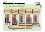
Page 14: ...t extinguished 1 Situate yourself near the receiver Turn on the Key to the ON position and push and pull the Stop push button The LED will light an instant in orange green after that it will blink in green colour and then it will get extinguished 4 The transmitter is now in change of frequency mode To modify the frequency first we press the upper left push button so many times like the number of d...

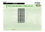
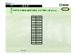
Page 15: ... FREQUENCIES 418MHz China TM70 FREQUENCIES 418MHz China CHART 11 II CHART 11 II Channel Freq MHz 1 418 950 2 418 975 3 419 000 4 419 025 5 419 050 6 419 075 7 419 100 8 419 125 9 419 150 10 419 175 11 419 200 12 419 225 13 419 250 ...

Page 16: ...75 23 433 600 24 433 625 25 433 650 26 433 675 27 433 700 28 433 725 29 433 750 30 433 775 31 433 800 32 433 825 33 433 850 34 433 875 35 433 900 36 433 925 37 433 950 38 433 975 39 434 000 40 434 025 Channel Freq MHz 41 434 050 42 434 075 43 434 100 44 434 125 45 434 150 46 434 175 47 434 200 48 434 225 49 434 250 50 434 275 51 434 300 52 434 325 53 434 350 54 434 375 55 434 400 56 434 425 57 434...

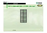
Page 17: ...Hz Korea TM70 FREQUENCIES 447MHz Korea CHART 11 IV CHART 11 IV Channel Freq MHz 1 447 600 2 447 625 3 447 650 4 447 675 5 447 700 6 447 725 7 447 750 8 447 775 9 447 800 10 447 825 11 447 850 12 447 875 13 447 900 14 447 925 15 447 950 16 447 975 ...

Page 18: ...IES 870MHz Europe TM70 FREQUENCIES 870MHz Europe CHART 11 V CHART 11 V Channel Freq MHz 1 869 70625 3 869 73125 5 869 75625 7 869 78125 9 869 80625 11 869 83125 13 869 85625 15 869 88125 17 869 90625 19 869 93125 21 869 95625 23 869 98125 ...

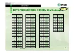
Page 19: ... 650 22 914 675 23 914 700 24 914 725 25 914 750 26 914 775 27 914 800 28 914 825 29 914 850 30 914 875 31 914 900 32 914 925 33 914 950 34 914 975 35 915 000 36 915 025 37 915 050 38 915 075 39 915 100 40 915 125 Channel Freq MHz 41 915 150 42 915 175 43 915 200 44 915 225 45 915 250 46 915 275 47 915 300 48 915 325 49 915 350 50 915 375 51 915 400 52 915 425 53 915 450 54 915 475 55 915 500 56 9...

Page 20: ...22 918 525 23 918 550 24 918 575 25 918 600 26 918 625 27 918 650 28 918 675 29 918 700 30 918 725 31 918 750 32 918 775 33 918 800 34 918 825 35 918 850 36 918 875 37 918 900 38 918 925 39 918 950 40 918 975 Channel Freq MHz 41 919 000 42 919 025 43 919 050 44 919 075 45 919 100 46 919 125 47 919 150 48 919 175 49 919 200 50 919 225 51 919 250 52 919 275 53 919 300 54 919 325 55 919 350 56 919 37...

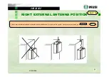
Page 21: ...12 CHART 12 9 Check that the external antenna is installed as described bellow in order to fix the system Once the system is fixed go to 9 Check that the external antenna is installed as described bellow in order to fix the system Once the system is fixed go to START START CHART 1 I CHART 1 I C8 ...

Page 22: ...I K U S I 22 21 05 2008 SPARE PARTS TOOLS SPARE PARTS TOOLS CHART 13 I CHART 13 I T70 1 transmitter CODE 2301090 T70 2 transmitter CODE 2309091 Transmitter spare parts Transmitter spare parts ...

Page 23: ...21 05 2008 SPARE PARTS TOOLS SPARE PARTS TOOLS CHART 13 II CHART 13 II Receiver Receiver spare parts spare parts LR72 XXX1 MHz receiver board CODE XXXXXXX1 1 Depending on the required frequency band Picture LR72 870 ...

Page 24: ...70 1 Industry standard Medium emision power ANTENNA TX 1 2303722 For T70 1 Industry High emision power ANTENNA TX 2 2303723 For T70 2 Construction standard High emission power ANTENNA Full 2303720 En T70 2 Industria estándar Potencia media ANT RX50 2303724 Receiver Construction standard High reception ANT RX 2303721 Receiver Industry standard Medium reception ...

Page 25: ...5 21 05 2008 SPARE PARTS TOOLS SPARE PARTS TOOLS CHART 13 IV CHART 13 IV TM70 TM70 external external antennas antennas MCX BNC cable for external antenna CODE 1095122 External antenna AE70 870 915MHz CODE 1119025 ...

Page 26: ...I 26 21 05 2008 SPARE PARTS TOOLS SPARE PARTS TOOLS CHART 13 V CHART 13 V Mechanical Mechanical tools tools P60 P70 push buttons tightening tool CODE 1179004 EMS60 STOP push button tightening tool CODE 1179007 ...

Page 27: ...27 21 05 2008 SPARE PARTS TOOLS SPARE PARTS TOOLS CHART 13 VI CHART 13 VI Eeprom Eeprom Software Hardware Software Hardware tools tools EP70 EEPROM recorder CODE 2309210 EP70 EEPROM recorder software TM70 Menu C8 ...

Reviews: