background image

Draco MultiView 4K

60


Operation via Management Software


171 

13.3.2  Restarting the Draco MV 

NOTICE 

When restarting the Draco MV, the current configuration is saved in the permanent memory of the 

Draco MV and the Draco MV will be restarted with the active configuration. 


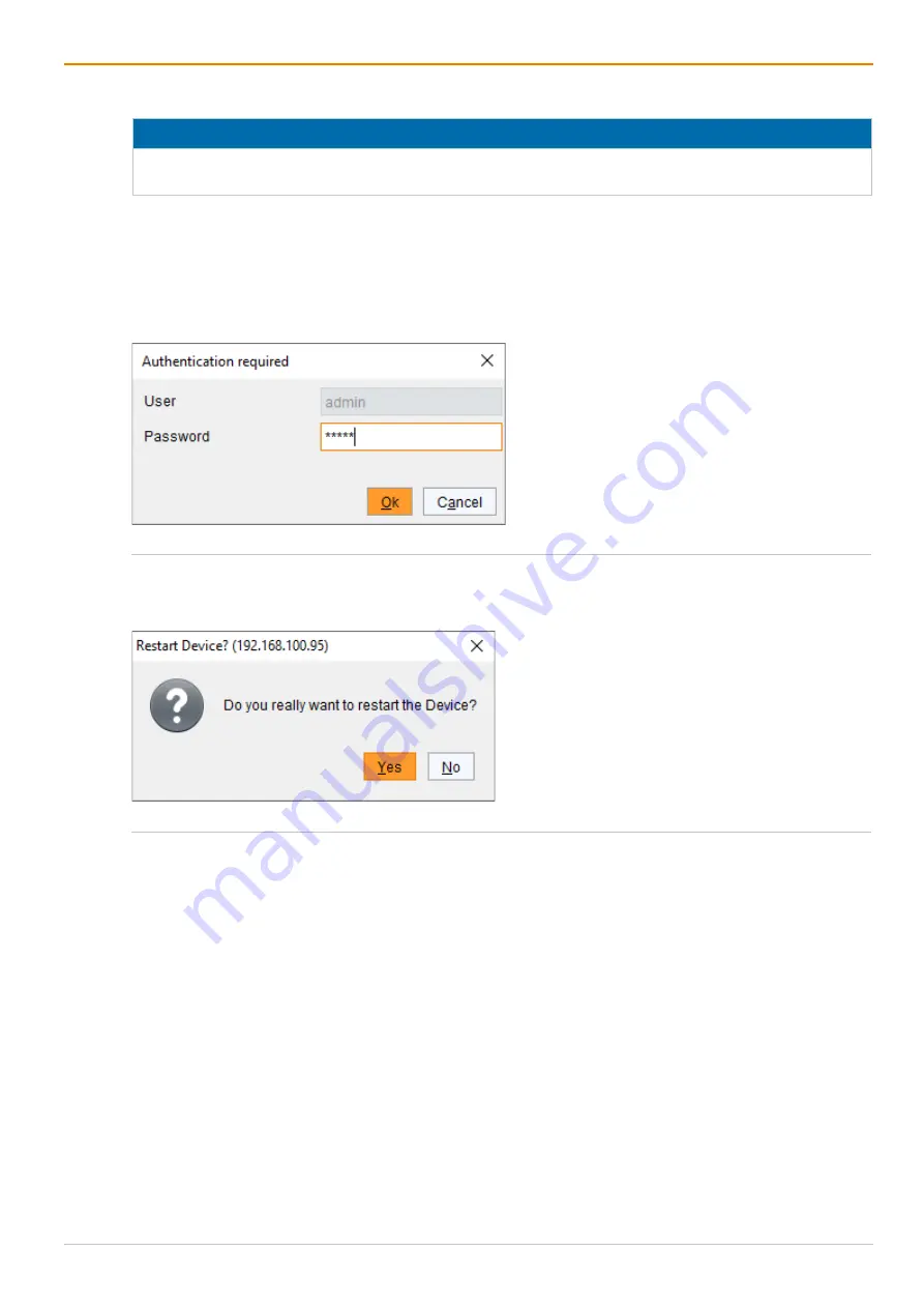
To perform a restart of the Draco MV, proceed as follows: 
1.  Click 

Device > Advanced Service > Restart Device

 in the menu bar. 

A login window appears. 

2.  Enter the username and password of the administrator. 
3.  Click 

Ok


Fig. 141  Management software dialog 

Log in administrator 


A query to restart the Draco MV appears. 

4.  Click 

Yes

 to restart the Draco MV. 


Fig. 142  Management software dialog 

Restart device 


The current configuration is saved in the permanent memory of the Draco MV and the Draco MV will be 
restarted. 


Summary of Contents for MV42 Series

Page 1: ...Document MV42_REV04 00_en Firmware version 01 08 Edition 2021 11 11 Software version 1 8 0 0 USER MANUAL Draco MultiView 4K60 KVM Switch Series MV42...

Page 2: ...ly described Please note the change log for this manual in chapter 22 page 225 The manufacturer reserves the right to change specifications functions or circuitry of the series described here without...

Page 3: ...in Picture 25 3 3 4 Display Mode PbP 2 2 Picture by Picture 27 3 3 5 Display Mode Preview 28 3 3 6 Display Mode Free 30 3 4 Installation Examples 32 3 4 1 Single Head Installation 32 3 4 2 Dual Head...

Page 4: ...ilter Function 56 4 3 9 Device Overview 57 5 Installation 60 5 1 Setting up the Draco MV 60 5 1 1 Connecting the Draco MV to the Sink and the Sources 60 5 1 2 Setting the Initial Configuration in the...

Page 5: ...gement Software 100 7 1 Configuring in Online Mode 100 7 2 Configuring in Offline Mode 101 7 3 Setting Management Software Options 102 7 3 1 Setting Program Default Settings 102 7 3 2 Setting Font Siz...

Page 6: ...158 10 7 2 Keyboard Commands for Operation 158 11 Operation via OSD 159 11 1 Focusing on one or two Inputs via OSD 159 11 2 Changing the Display Mode via OSD 161 11 3 Powering Down Restarting and Rese...

Page 7: ...3 6 Updating the Firmware via Management Software 194 15 3 7 Resetting the Draco MV to the Factory Settings 197 15 4 Querying the System Status via API Interface 198 15 4 1 Status Request Response Fr...

Page 8: ...B 214 17 2 6 Mini USB Type B 214 17 2 7 D Sub 9 GPIO 214 17 2 8 Mini Toslink 214 17 2 9 RJ45 Network 215 17 3 Power Supply Voltage and Power Consumption 215 17 4 Environmental Conditions and Emission...

Page 9: ...function variants This symbol indicates instructions for procedures recommended by the manufacturer for an effective utilization of the device potential 1 3 Terms and Spellings Uniform terms are used...

Page 10: ...lbar e g Extras Options Mouse button Description Left mouse button Primary mouse button default in most operating systems Right mouse button Secondary mouse button Unless you have customized your mous...

Page 11: ...re likely to be present CAUTION Risk of burns due to tremendously heated chassis surface after a long period of operation The surface of the chassis can become very warm after a long period of operati...

Page 12: ...r approved replacements Connect all power supply units to grounded outlets Ensure that the ground connection is maintained from the outlet socket through to the power supply unit s AC power input Disc...

Page 13: ...switching status see accessories list in chapter 3 6 page 36 Alternatively there is an API interface available over TCP IP NOTICE Interferences when the immunity limit values are exceeded If the limit...

Page 14: ...nnected to the Draco MV via provided USB and video cables Monitors keyboard mouse and optional audio devices are also connected directly to the Draco MV The Draco MV manages the switching commands and...

Page 15: ...rnal control via TCP IP using a Cat X network cable via API interface Fig 2 System overview example Dual Head installation with external controls 1 Sources computer graphic card 2 Draco Multiview 4K60...

Page 16: ...rimary video audio board 4 Monitor 2 OUT2 1 secondary video audio board 5 Audio output of the primary video audio board 6 Audio 1 OUT1 1 primary video audio board 7 Audio 2 OUT2 1 primary video audio...

Page 17: ...ay to stream up to four video signals 1 Monitor 2 Display 3 Window with streamed video signal The Source Name option shows the associated input name of a window We recommend activating this option esp...

Page 18: ...he internal window arrangement remains with focused window Video outputs All video outputs get the information of the changed window arrangement No reaction Main monitor Depending on the current displ...

Page 19: ...st be configured in the operating system of the respective computer in each case There are the following possibilities for the audio output Audio signal of the currently active source The audio signal...

Page 20: ...No audio output 2 Channel audio amalgamated Video output 2 via monitor Up to 7 1 Channel audio No audio output 2 Channel audio amalgamated Audio output 1 with analog audio device 2 Channel audio No au...

Page 21: ...ith a second monitor at the secondary output without audio mixing 3 3 1 Display Mode Fullscreen Assignment of Inputs to Outputs In Fullscreen display mode referred to as Fullscreen Mode below the wind...

Page 22: ...with two selected inputs the window arrangement changes For instance when focusing from input 1 to input 4 the main window streams the video signal of the selected input Monitor 2 shows a mirrored ima...

Page 23: ...ocused input and the mouse can be used within the associated window Fig 8 Fullscreen Mode individual to individual Example after focusing on two other inputs To keep the display mode and select two in...

Page 24: ...ce when switching the USB HID control from input 1 to input 4 the mouse can be used within the associated window Fig 10 Quad Mode Example after switching the USB HID control or focusing on another inp...

Page 25: ...Monitor 2 shows a mirrored image of the main monitor Fig 11 PiP Mode Window arrangement Switching of the USB HID Control In PiP Mode the window arrangement remains after switching the USB HID control...

Page 26: ...dow Fig 13 PiP Mode Example after focusing on another input To keep the display mode and focus on another input there are the following possibilities Focusing on another input via keyboard command see...

Page 27: ...tance when switching the USB HID control from input 1 to input 4 the mouse can be used within the associated window Fig 15 PbP Mode Example after switching the USB HID control or focusing on another i...

Page 28: ...The preview window of the focused input shown on the main monitor is displayed in black by default Fig 16 Preview Mode Window arrangement Switching of the USB HID Control In Preview Mode the window a...

Page 29: ...d in black Fig 18 Preview Mode Example after focusing on another input To keep the display mode and focus on another input there are the following possibilities Focusing on another input via keyboard...

Page 30: ...zooming Monitor 2 shows a mirrored image of the main monitor Fig 19 Free Mode Window arrangement Switching of the USB HID Control Keeping the Windows Arrangement In Free Mode the window arrangement re...

Page 31: ...Mode Example after focusing on another input To keep the display mode and focus on another input there are the following possibilities Switching via keyboard command see chapter 10 1 page 146 Switchin...

Page 32: ...Head installation consists of a Draco MV up to four sources and one console maximum 2 monitors 1 keyboard 1 mouse 2 audio output devices The Draco MV is directly connected to the sources and the cons...

Page 33: ...th second monitor per video board 1 Source 1 2 Source 2 3 Source 3 4 Source 4 5 Draco Multiview 4K60 6 USB HID devices e g keyboard mouse 7 Audio device 1 e g speaker primary video audio board 8 Main...

Page 34: ...d with an optional external switching solution via dry contact or via external control Fig 24 System overview example Single Head installation with external controls 1 Source 1 2 Source 2 3 Source 3 4...

Page 35: ...overview example Dual Head installation with external controls 1 Source 1 2 Source 2 3 Source 3 4 Source 4 5 Draco Multiview 4K60 6 External switching solution optional 7 USB HID devices e g keyboard...

Page 36: ...Male with 8x GPIO MV42 H2SH Input 4x HDMI 2 0 with 4K60 4x USB Type B Output 2x HDMI 2 0 with 4K60 4x USB Type A each 2x USB HID USB 2 0 2x audio 3 5 mm optical digital analog Input Output 1x DB9 Mal...

Page 37: ...ry may vary depending on country of delivery and customer specification Product type Scope of delivery MV42 DPSH Draco MultiView 4K60 2x IEC country specific power cord C13 2 0 m lockable 4x DisplayPo...

Page 38: ...nts with video audio inputs and outputs details see below chapters 3 Ports for network and power supply voltage 3 9 2 Ports for CPUs USB Devices Service and External Switching Solution Fig 28 Interfac...

Page 39: ...e side Ports for DisplayPort 1 2 Dual Head 1 IN1 1 DP 1 2 input 1 from source 1 2 IN2 1 DP 1 2 input 1 from source 2 3 IN3 1 DP 1 2 input 1 from source 3 4 IN4 1 DP 1 2 input 1 from source 4 5 OUT1 1...

Page 40: ...rts for HDMI 2 0 Dual Head 1 IN1 1 HDMI 2 0 input 1 from source 1 2 IN2 1 HDMI 2 0 input 1 from source 2 3 IN3 1 HDMI 2 0 input 1 from source 3 4 IN4 1 HDMI 2 0 input 1 from source 4 5 OUT1 1 HDMI 2 0...

Page 41: ...y 3 10 Device Status Indication 3 10 1 USB HID Control Fig 34 Interface side Status LED for switching 1 LED for the USB HID control Status LED for the Switching Status of the USB HID Control Pos LED S...

Page 42: ...board Status LEDs for USB HID Control and System Status Pos LED Status Description 1 4 USB HID control Off No USB HID control of the associated input available Green The USB HID control is switched t...

Page 43: ...l for input CPU3 9 LED USB HID control for input CPU4 10 LED system status of the secondary video audio board Status LEDs for USB HID Control and System Status Pos LED Status Description 1 4 6 9 USB H...

Page 44: ...o board Status LEDs for USB HID Control and System Status Pos LED Status Description 1 4 USB HID control Off No USB HID control of the associated input available Green The USB HID control is switched...

Page 45: ...nput CPU3 9 LED USB HID control for input CPU4 10 LED system status of the secondary video audio board Status LEDs for USB HID Control and System Status Pos LED Status Description 1 4 6 9 USB HID cont...

Page 46: ...activity LED Pos 2 for the respective situation Pos 1 Pos 2 Description Off Off No network connection available Green Off Network connection available no data traffic available Green Orange Network c...

Page 47: ...from the link https www ihse com software Advanced settings can be configured on the Draco MV operating system using the management software Advanced configuration Extended monitoring options System...

Page 48: ...the Hot Key Function Keyboard command 2x Left Shift Hot Key factory setting Start the command mode Esc Exit the command mode current Hot Key c new Hot Key Code Enter Change the Hot Key NOTICE If inst...

Page 49: ...he position of the keys on the keyboard Keyboard mapping tables may vary for country specific layouts Note the key position of a freely defined Hot Key when changing the keyboard layout e g from QWERT...

Page 50: ...Keyboard command Function Hot Key o Open the OSD Esc Exit the OSD in the main menu or go back one step in the menu structure Left Shift Esc Exit the OSD within the menus Left Ctrl Esc NOTICE If the OS...

Page 51: ...option in selection fields Previous option in selection fields Spacebar Switching in selection fields between two conditions e g between ON OFF or Y Yes N No Enter In menus with input fields save data...

Page 52: ...ject changes Okay Confirm changes temporary storage of the active configuration in the volatile memory of the Draco MV NOTICE Possible loss of configuration changes By clicking Okay changes are overta...

Page 53: ...ing control elements are included in the menus Designation Element Description Checkbox Function is not active disabled by default or by mouse click Function is active enabled by default or by mouse c...

Page 54: ...names tooltips for the menu items can be activated under Extras Options on the Style tab Online help After calling up a function from the task area a menu opens in the work area of the management sof...

Page 55: ...n In input or status menus with more than one page next page Tab In input menus previous field Left Shift Tab In input menus next field Spacebar Switch in selection fields between two conditions check...

Page 56: ...ascending order The sorting is indicated by an arrow pointing upwards Descending sort Click with the left mouse button twice on the header of the column to be sorted The column is sorted in descendin...

Page 57: ...ps Displaying the current USB HID control Displaying the current display mode Displaying the routing from an input to an output Selecting a second input for the Fullscreen Mode Changing the display mo...

Page 58: ...he main window displays the video signal of input 3 Fig 44 Preview Mode Example for device status with switched input 3 1 Display of the routing to the primary output 2 Display of the routing to the s...

Page 59: ...ected or the connected source is switched off A source is connected and the source is switched on No monitor is connected or the connected monitor is switched off A monitor is connected and the monito...

Page 60: ...age 14 NOTICE Scaled video resolution when using different monitor resolutions The video output adjusts to the resolution of the monitor with the lower preferred timing For optimal functionality of sw...

Page 61: ...the system Setting up the GPIO Module optional The GPIO module can be hot plugged 5 1 2 Setting the Initial Configuration in the OSD To configure the initial settings in the OSD proceed as follows 1...

Page 62: ...memory RAM Recommended 512 MB Operating system Microsoft Windows 8 Windows 8 1 Windows 10 Management software with integrated Java Runtime Draco MV Tool Downloaded from https www ihse com software Ne...

Page 63: ...irewall If using the management software the Java application file javaw exe has to be released in the firewall settings to use the management software Contact your administrator to configure the fire...

Page 64: ...ement software by a double click on the program icon on the desktop or the file in the directory The management software starts in offline mode Fig 46 Management software Landing page in offline mode...

Page 65: ...ing to the network configuration of the Draco MV see chapter 6 2 2 page 73 By default the IP address of the Draco MV is 192 168 100 95 and DHCP is deactivated 4 Enter the username and password of the...

Page 66: ...ld be accessed via IP Fig 48 Management software menu Device Finder The following device information is shown in the Device Finder Information Description Broadcast Multicast Search parameters for fin...

Page 67: ...cast address By default the search is set via broadcast 255 255 255 255 3 Click Connect in the last column of the Device Finder to establish direct connection to the respective device within the same...

Page 68: ...arted The restart of the Draco MV may take several minutes and the Draco MV is not available during the restart All configuration settings can only be configured with administrator rights The followin...

Page 69: ...ation Menu Various options for system setting are available in the configuration menu In addition the following functions can be called up here save as active or predefined configuration and shut down...

Page 70: ...guration that is used to save the current settings default Standard Info Text Enter additional text to describe the configuration if required default Factory settings Load Default Y Start the Draco MV...

Page 71: ...ndow into another window the USB HID control switches seamlessly to the associated input N Function not active default Relative mouse coordinates are used For Dual Head installations MSC is recommende...

Page 72: ...efault 5 Double Click Time ms 100 to 800 Adjust the time slot for a double click default 200 Keyboard Layout Region Set the OSD keyboard layout according to the keyboard used default German DE Hot Key...

Page 73: ...e logging will be started after restarting the Draco MV The parameters for the network configuration are set in this menu Fig 52 OSD Menu Configuration Network The following parameters can be configur...

Page 74: ...ver for status requests N Function not active default Syslog Server 1 2 Byte Enter the IP address of the Syslog servers in the form 192 168 1 1 and of the Syslog port default 514 Log Levels Field Entr...

Page 75: ...ew 4K60 Configuration via OSD 75 To set parameters for the network configuration proceed as follows 1 Select Configuration Network in the main menu 2 Change the desired settings 3 Click Okay to confir...

Page 76: ...ent Y Enable the network time server synchronization N Function not active default SNTP Server Byte Enter the SNTP server IP address default 000 000 000 000 Time Zone Region Set your specific time zon...

Page 77: ...in the Time Zone field 5 Click Okay to confirm your settings 6 Restart the Draco MV The system time will now be provided by the SNTP server Configuring the Real Time Clock without Time Server To set...

Page 78: ...aseline Protection is recommended The read only community for the MIB file is draco NOTICE For an activation of the SNMP agent function or the SNMP server function a restart of the Draco MV is necessa...

Page 79: ...itched on console Remove Output Notification about a removed console from the Draco MV Notification about a switched off console Input Video Info Notification about a change of resolution or change of...

Page 80: ...SD Gain 0 to 100 Intensity of the transparency Source Names Field Entry Description Enable Activated The source names are displayed at the top left of the respective window Option for all display mode...

Page 81: ...cept for the Fullscreen Mode Option for all display modes except for the mirrored Fullscreen Mode Deactivated Function not active default Color List Frame color for active source The frame is displaye...

Page 82: ...of up to 16 characters Repeat Password Text Repeat user password case sensitive SNMPv3 user The SNMPv3 user username snmp has the permission to enable encrypted SNMPv3 The following parameters can be...

Page 83: ...e transmitted Ensure the login data username and password in both settings are identical see section on page 75 Editing User Settings To edit settings of an existent user proceed as follows 1 Select C...

Page 84: ...x 1080 60 Hz Instead of the current EDID a customized EDID will be transmitted to the sources 1440p60 2560 x 1440 60 Hz 4K30 3840 x 2160 30 Hz 4K60 3840 x 2160 60 Hz No Signal Color List Background c...

Page 85: ...080p60 1920 x 1080 60 Hz Instead of the default EDID set at the video input the video signal will be scaled up or down at the video output 1440p60 2560 x 1440 60 Hz 4K30 3840 x 2160 30 Hz 4K60 3840 x...

Page 86: ...nditions when creating and arranging a layout in Free Mode see chapter 10 5 page 153 6 5 1 Displaying the Free Mode initially When displaying the Free Mode for the first time the windows are displayed...

Page 87: ...displayed in the edit mode Fig 60 Free Mode Example after activating the edit mode To exit the edit mode in Free Mode proceed as follows Press Ctrl Esc Changes of layouts remain without saving In the...

Page 88: ...of displaying a window in full screen 2 Click and hold down the right mouse button and drag to draw a rectangle around the desired area 3 Press Enter to crop the rectangle area The cropped area is dis...

Page 89: ...ndow hold down the left mouse button and move to mouse to resize the window Fig 64 Edit mode in Free Mode Example after scaling a cropped window with aspect ratio 2 Scaling without aspect ratio Click...

Page 90: ...g 66 Edit mode in Free Mode Example of moving a scaled window The windows of input 1 to input 4 are internally arranged in levels Input 1 Input 2 Input 3 Input 4 Window Window 1 Window 2 Window 3 Wind...

Page 91: ...gle the window level of an input between foreground and background by using the respective numbers on the keyboard Using the numerical pad will not work Example The following figures show a created Fr...

Page 92: ...ple after resetting a cropped area back to full screen Resetting via Backspace resets always the window in which the OSD mouse is located Possibility 2 Click the left and right mouse buttons simultane...

Page 93: ...ated edit mode there are the following possibilities to open a layout Possibility 1 1 Press Ctrl o A dialog appears Fig 71 OSD Menu Free Mode Edit Mode Open Layout 2 Select one of the Free Mode layout...

Page 94: ...ut proceed as follows 1 Press Ctrl s A dialog appears Fig 72 OSD Menu Free Mode Edit Mode Save Layout 2 Select a storage slot to save the layout 3 Option enter a name for the layout input of up to 16...

Page 95: ...ry settings and the video signal is displayed in the current resolution 3 To reset all layouts click Reset All All layouts are reset to the factory settings and the video signals are displayed in the...

Page 96: ...he information that unsaved changes will be lost without saving Fig 74 OSD Menu Free Mode Edit Mode Close Free Mode 2 Click Discard changes to exit the edit mode without saving the latest changes The...

Page 97: ...ollowing possibilities to save configuration changes Saving the current configuration permanently in the Draco MV memory Saving the configuration in up to 8 predefined storage locations as well as the...

Page 98: ...to the selected memory location and is immediately displayed in this menu The configuration previously saved at this memory location is overwritten However saving predefined configurations does not re...

Page 99: ...iously saved configurations are loaded in this menu In Active the currently loaded configuration is displayed To replace the current configuration by another configuration in addition to the default c...

Page 100: ...o MV is not available during the restart 7 1 Configuring in Online Mode Configurations and system settings can be edited via management software in online mode with an active connection between Draco...

Page 101: ...ic configuration Factory Settings saved on the Draco MV is loaded into the management software 2 Click Download in the toolbar to download the configuration A new tab will be opened with the downloade...

Page 102: ...efault Settings The following parameters can be configured Option Description IP Hostname Default IP address or host name of the Draco MV for establishing a connection User Default username for establ...

Page 103: ...Extras Options in the menu bar and click the Style tab 2 Select the desired font size Normal or Large 3 Check the Show Toolbar Button Text checkbox to show a tooltip when hovering over a menu item in...

Page 104: ...nu The charset must match the selected language to ensure correct representation 1 Click Extras Options in the menu bar and click the Language tab 2 Select the desired language within the management s...

Page 105: ...management software proceed as follows 1 Click Extras Options in the menu bar and click the Miscellaneous tab 2 Check the Device Finder on startup checkbox 3 Click Ok to confirm the changes 4 Close t...

Page 106: ...rameters can be configured System Settings Parameter Entry Status Description Device Text Enter the device name of the Draco MV default DPSWITCH 01 Name Text Enter the name of the configuration that i...

Page 107: ...eactivated Function not active default Enable MSC Activated Enable Multi Screen Control Absolute mouse coordinates are used for the MSC automatic mode with without restriction see chapter 9 page 141 M...

Page 108: ...s follows 1 Click Configuration System in the task area 2 Click Activate Edit Mode in the toolbar 3 Change the desired settings 4 Click Apply to confirm the changes 5 Click Deactivate Edit Mode in the...

Page 109: ...tem Settings Network General The following parameters can be configured Network Settings Field Entry Description DHCP Activated The network settings are automatically supplied by a DHCP server Note If...

Page 110: ...ctivated Function not active SSL Support Activated Activate SSL encryption for API management software API management software and Draco MV communication Deactivated Function not active default Mainte...

Page 111: ...not active default Syslog Server Byte Enter the IP address of the Syslog servers in the form 192 168 1 1 Port Byte Enter the Syslog ports default 514 Log Level Debug Activate debug messages in Syslog...

Page 112: ...ing the Syslog Options To set or activate the presetting proceed as follows 1 Click Extras Options in the menu bar and click the Syslog tab 2 Enter the appropriate data 3 Click Ok to confirm the entri...

Page 113: ...Log Files Allowed maximum number of log files When the maximum number of log files is exceeded the oldest log file will be overwritten with the new information log rotate Acoustic Notification Enable...

Page 114: ...standard Two SNMP servers can be used at the same time NOTICE When using SNMP monitoring for reasons of access security the use of a dedicated network according to the IT Grundschutz Kompendium IT Bas...

Page 115: ...switching operation at the Draco MV Output Inserted Notification about a console newly connected to the Draco MV Notification about a switched on console Output Removed Notification about a console r...

Page 116: ...der SNMP Server 6 Check the checkboxes of the desired traps to activate them 7 Click Apply to confirm the changes 8 Click Deactivate Edit Mode in the toolbar Setting up SNMP Options Presets for an SNM...

Page 117: ...m Log File Size KB Allowed maximum size of log file When reaching the maximum log file size a new log file will be created Maximum Number of Log Files Allowed maximum number of log files When the maxi...

Page 118: ...Ensure the login data username and password in both settings are identical see chapter 0 page 128 Fig 88 Management software menu Extras Options SNMP Manage SNMPv3 Users Add User The following parame...

Page 119: ...Options in the menu bar and click the SNMP tab 2 Click Manage SNMPv3 Users A list appears with already created SNMPv3 users 3 Click Add User A dialog window appears 4 Enter the required data and click...

Page 120: ...ime The following parameters can be configured SNTP Field Entry Status Description SNTP Activated Network time server synchronization Deactivated Function not active default SNTP Server Byte SNTP serv...

Page 121: ...lick Apply to confirm your settings 7 Restart the Draco MV The system time is now provided by the SNTP server Configuring the Real Time Clock without Time Server To set the real time clock without usi...

Page 122: ...outside the OSD Intensity 0 to 100 Intensity of the transparency Source Names Field Entry Status Description Enable Activated The source names are displayed at the top left of the respective window O...

Page 123: ...ctive default Color List Frame color for active source The frame is displayed for the current session After a restart the frame must be reactivated if necessary OSD Cursor Field Entry Description Colo...

Page 124: ...d in during operation the monitor s EDID is read out and transmitted to the CPU inputs The video signal is always displayed with the native resolution of the currently connected monitor 1080p60 1920 x...

Page 125: ...tion of the video output is set to 4K60 If a 4K60 monitor is connected to the output the video signal is scaled to 4K60 If there is no video signal input a notification is displayed NO SYNC OR SIGNAL...

Page 126: ...the lower set resolution MONITOR Instead of the default EDID set at the video input the video signal is displayed with the native resolution of the currently connected monitor 1080p60 1920 x 1080 60 H...

Page 127: ...ut proceed as follows 1 Click Input Output Controls Output Control in the task area 2 Click Activate Edit Mode in the toolbar 3 Select the video input to be configured in the list Output Devices 4 Cha...

Page 128: ...Field Entry Description Full Name Text Optional personal username case sensitive up to 32 characters Password Text User password case sensitive input of up to 16 characters SNMPv3 User The SNMPv3 use...

Page 129: ...user are different between the Draco MV and the SNMP server no SNMP loggings are transmitted Ensure the login data username and password in both settings are identical see page 118 Editing User Settin...

Page 130: ...guration into up to 8 predefined storage locations as well as the default configuration into the Draco MV memory Upload saving the configuration into a local memory Save or Save as 7 7 1 Saving the Cu...

Page 131: ...Output Controls Input Control Output Control User Settings User To save a configuration file locally proceed as follows 1 Click File Save As in the menu bar 2 Enter a name for the configuration 3 Sel...

Page 132: ...ion file into the management software 7 7 4 Uploading a Predefined Configuration to the Draco MV Using the function Upload the created configuration can be saved within eight storage locations in the...

Page 133: ...immediately check the Activate configuration after upload checkbox NOTICE If you activate the Activate configuration after upload option the Draco MV will be restarted immediately after the save proc...

Page 134: ...uration A query to restart the Draco MV appears 4 Click Yes to confirm the restart The connection is disconnected and the Draco MV is restarted The selected configuration is loaded on restart and is s...

Page 135: ...the toolbar A login window appears 2 Enter the IP address of the Draco MV 3 Enter the username and password of the administrator 4 Click Next to display the selection of storage location Fig 100 Mana...

Page 136: ...will be saved as config dmc configurations stored in the slots Default or File 1 to File 8 are saved as default dmc or config01 dmc to config08 dmc in the zip file To save a status proceed as follows...

Page 137: ...k Next Fig 103 Management software menu Save Status Anonymization 4 Wait until all steps show green check marks and the Saving status successful message is displayed 5 Click Finish to complete the sav...

Page 138: ...to the storage location of the status file to be opened 3 Click the status file to be opened 4 Click Open to open the status file Fig 105 Management software menu Device Load Status The status can als...

Page 139: ...arameters To activate or deactivate the routing of the USB 2 0 ports to the four USB B ports a parameter can be entered in the configuration file Config txt The following parameter settings are availa...

Page 140: ...containing the Config txt file 2 Open the Config txt file in a text editor 3 Ensure that CFG is written in the first line of the file 4 Add a line break directly behind CFG 5 Add the desired paramete...

Page 141: ...ctivating MSC or restricting the automatic mode of MSC see following page The descriptions in the following sections refer to the desktop arrangement set in the source operating system Monitor1 Monito...

Page 142: ...icted to the windows associated to the input with the current USB HID control and cannot be moved over the edge of a window The Hot Mouse function cannot be used To restrict the automatic mode of enab...

Page 143: ...input and displaying the video signal on the main window Switching from an Input with current USB HID Control to another Input To open the OSD with the Switch menu proceed as follows 1 Move the mouse...

Page 144: ...should be displayed on the main window 1 Move the mouse to another window e g the window associated to input 2 The Hot Mouse function with a transparency overlay and the OSD mouse pointer is activate...

Page 145: ...e OSD mouse into the window 3 The video signal of input 3 is shown in the main window and the window order of the small windows is changed The Hot Mouse function turns automatically off and the USB HI...

Page 146: ...ps Lock and Scroll Lock LEDs on the keyboard are flashing 2 On the numeric keypad press the number of the USB input to which you want to switch the USB HID control e g NUM2 The USB HID control is swit...

Page 147: ...amed in the window on the main monitor Monitor 2 shows a mirrored image of the main monitor The USB HID control is switched to the selected input Both audio outputs output the audio signal of the inpu...

Page 148: ...cted input is displayed on the main window and the small windows change in numeric order Fig 118 PiP Mode Example after focusing on another input Example for Focusing on another Input in Free Mode In...

Page 149: ...al situation in Preview Mode the active window shows the video signal from input 1 and the USB HID control is switched to input 1 To focus on another input with a function key proceed as follows 1 Pre...

Page 150: ...Key 13 Enter Focus on input 1 Display the associated window of input 3 Hot Key 14 Enter Focus on input 1 Display the associated window of input 4 Hot Key 21 Enter Focus on input 2 Display the associat...

Page 151: ...utput 2 is displayed on monitor 2 The command mode is closed and the keyboard LEDs returned to their previous status Fig 121 Fullscreen Mode with two selected inputs Example for switching 10 4 Changin...

Page 152: ...Changing the display mode from the Preview Mode to the Quad Mode Example 2 In the initial situation in Preview Mode the main window shows the video signal from input 1 and the USB HID control is swit...

Page 153: ...ouse Move the mouse pointer over the edge of a window into another window to switch the USB HID control to another USB input The USB HID control will be switched seamlessly allowing full control of th...

Page 154: ...ot Key Code table Hot Key c 0 new Hot Key Enter Define a freely selectable Hot Key Right Shift Del within 5 s after plugging in a keyboard Reset the Hot Key back to default settings Fast Key Keyboard...

Page 155: ...utomatic switching of activated MSC enable the automatic switching The mouse can be moved over the edge of a window and the Hot Mouse function can be used if activated Switching the USB HID Control Ke...

Page 156: ...Hot Key 33 Enter Focus on input 3 Display the associated window of input 3 Hot Key 34 Enter Focus on input 3 Display the associated window of input 4 Hot Key 41 Enter Focus on input 4 Display the asso...

Page 157: ...edit mode save the layout ESC With activated edit mode exit the edit mode discard or save changes Ctrl 1 With activated edit mode open the Free Mode layout 1 Ctrl 2 With activated edit mode open the F...

Page 158: ...and the Hot Mouse function can be used if activated 10 7 2 Keyboard Commands for Operation Keyboard command Function 2x Left Shift Start the command mode Hot Key factory setting Esc Exit the command...

Page 159: ...is opened on the main monitor showing the Switch menu 4 Select the input in the OUT 1 1 list under Source Selection that has to be routed to the main output 5 Press Enter The USB HID control is switc...

Page 160: ...the input in the OUT 1 1 list under Source Selection that has to be routed to the main output 3 Select the input in the OUT 2 1 list under Source Selection that has to be routed to the secondary outp...

Page 161: ...possibilities Changing the display mode retaining the current USB HID control Changing the display mode and switching the current USB HID control with one or two inputs Changing the Display Mode Retai...

Page 162: ...2 Select the desired input for the main output OUT1 x under Source Selection 3 Click the desired display mode under Display Mode or press the respective function key e g F4 displays the Preview Mode T...

Page 163: ...output 3 Select the input for the second output OUT2 x under Source Selection that has to be routed to the secondary output 4 Click Fullscreen under Display Mode or press the respective function key F...

Page 164: ...co MV and the Draco MV will be shut down NOTICE After shutting down the Draco MV can be disconnected from the power supply voltage Fig 128 OSD Menu Configuration Shut down MV 11 3 2 Restarting the Dra...

Page 165: ...17 2 7 page 214 for the pin assignment By pressing a push button the USB HID control is switched to the associated input the video signal of the associated input is focused on the window arrangement a...

Page 166: ...in Fullscreen Mode individually Right mouse button focusing on one input and change to the Fullscreen Mode Fig 130 Management software Device Status Focusing on another Input To focus on another inpu...

Page 167: ...sired output e g main output The available ports for switching are highlighted in green without red cross 3 Release the mouse button A context menu shows the available display mode for this switching...

Page 168: ...g are highlighted in green without red cross 3 Release the mouse button A context menu shows the available display mode for this switching procedure 4 Click Fullscreen in the context menu to focus on...

Page 169: ...ground in Free Mode or on the main window in Fullscreen Mode Preview Mode and PiP Mode To change the display mode proceed as follows 1 Click Status Updates Device Status in the task area 2 Click the d...

Page 170: ...wn Device in the menu bar A login window appears 2 Enter the username and password of the administrator 3 Click Ok Fig 138 Management software dialog Log in administrator A query to shut down the Drac...

Page 171: ...art of the Draco MV proceed as follows 1 Click Device Advanced Service Restart Device in the menu bar A login window appears 2 Enter the username and password of the administrator 3 Click Ok Fig 141 M...

Page 172: ...ia control will just be routed through to the target computer To route the USB 2 0 device through to the desired target computer proceed as follows 1 Switch the USB HID control to the desired target c...

Page 173: ...o the selected input The focusing results are described in the respective sections API 7 byte telegram 07 06 05 04 03 02 01 Function 1B 5B 47 07 00 01 00 Focus on input 1 1B 5B 47 07 00 02 00 Focus on...

Page 174: ...sociated window of input 3 1B 5B 47 07 00 18 00 Focus on input 2 Display the associated window of input 4 1B 5B 47 07 00 1F 00 Focus on input 3 Display the associated window of input 1 1B 5B 47 07 00...

Page 175: ...0 The associated window of input 2 is maximized in the window arrangement on the main monitor connected to the main output The USB HID control is connected to the associated input The associated windo...

Page 176: ...09 00 00 00 00 00 ModeID 0 Fullscreen 1B 5B 46 09 00 01 00 00 00 ModeID 1 n a 1B 5B 46 09 00 02 00 00 00 ModeID 2 PiP 1B 5B 46 09 00 03 00 00 00 ModeID 3 Quad 1B 5B 46 09 00 04 00 00 00 ModeID 4 n a...

Page 177: ...2 Change to layout 3 in Free Mode 03 Change to layout 4 in Free Mode 14 2 3 Keeping Switching the USB HID Control Byte 2 Function 00 Keep the USB HID control at the current USB input 01 Switch the USB...

Page 178: ...3 00 01 00 Focus on input 3 on the main output OUT1 x 1B 5B 50 09 00 04 00 01 00 Focus on input 4 on the main output OUT1 x 1B 5B 50 09 00 01 00 02 00 Display the associated window of input 1 on OUT2...

Page 179: ...s and add on modules as well as the accessories can be damaged by cleaning with damp or aggressive cleaning agents If the chassis is nevertheless cleaned with damp or aggressive cleaning agents and da...

Page 180: ...s displayed in this menu Select Status Video in the main menu to query the resolution of the video signals and the monitor information Fig 147 OSD Menu Status Video 15 2 2 Querying the Network Status...

Page 181: ...Draco MultiView 4K60 Maintenance 181 Fig 148 OSD Menu Status Network For information about the parameters please refer to chapter 6 2 2 page 73...

Page 182: ...tenance Draco MultiView 4K60 182 15 2 3 Querying the SNMP Status The current SNMP status is displayed in this menu Select Status SNMP in the main menu to query the SNMP status Fig 149 OSD Menu Status...

Page 183: ...w 4K60 Maintenance 183 15 2 4 Querying the Firmware Status The current firmware status is displayed in this menu Select Status Firmware in the main menu to query the firmware status Fig 150 OSD Menu S...

Page 184: ...splayed in this menu The procedure for activating the SNMP agent or configuring an SNMP server is described in chapter 6 2 4 page 78 Select Status Trace in the main menu to display the recorded events...

Page 185: ...IP address and the admin password NOTICE If a firmware update has been carried out since the delivery the latest installed firmware version is retained To perform a reset of the Draco MV proceed as fo...

Page 186: ...e Video Status can be queried in the Web UI 15 3 2 Querying the Network Status The current network configuration is displayed in this menu Click System Settings Network in the task area to query the n...

Page 187: ...3 Querying the Firmware Status The current firmware status is displayed in this menu Click Status Updates Firmware Update in the task area to query the current firmware status Fig 154 Management soft...

Page 188: ...tinuously into log files and stored locally NOTICE Syslog messages are transmitted via UDP Therefore port 514 within the used network should not be blocked e g by a firewall The procedure for activati...

Page 189: ...r a defined severity will be filtered Host Messages for a defined host will be filtered Message Messages with defined text parts will be filtered Filter options are not valid within the locally stored...

Page 190: ...k Monitoring in the toolbar 2 Click the Find tab in the working area The recorded Syslog messages are displayed in the working area 3 Enter a search term in the Find Message search field 4 Click Find...

Page 191: ...cess security the use of a dedicated network according to the IT Grundschutz Kompendium IT Baseline Protection is recommended The read only community for the MIB file is draco The procedure for activa...

Page 192: ...Messages for a defined severity will be filtered Host Messages for a defined host will be filtered Message Messages with defined text parts will be filtered Filter options are not valid within the lo...

Page 193: ...1 Click Monitoring in the toolbar 2 Click the Find tab in the working area The recorded SNMP messages are displayed in the working area 3 Enter a search term in the Find Message search field 4 Click...

Page 194: ...se please contact the manufacturer s technical support in advance If required the update files can be requested from the manufacturer s technical support NOTICE To process successful firmware updates...

Page 195: ...agement software All updateable firmware parts of the Draco MV will be automatically selected and highlighted in green 3 Option deselect individual firmware parts of the Draco MV if not all firmware p...

Page 196: ...ation is shown in the update log in the lower area of the working area Repeat the update observing to the required sequence HUSWMSD pfw further firmware Example for possible error messages Fig 162 Man...

Page 197: ...latest installed firmware version is retained To perform a reset of the Draco MV proceed as follows 1 Click Device Advanced Service Factory Reset in the menu bar A login window appears 2 Enter the us...

Page 198: ...ement at all outputs Fig 167 Example API telegram with status request and response Assignment of Bytes and used Abbreviations In the following chapters we use abbreviations for byte assignment in the...

Page 199: ...2 12 MV42 DPSH Draco MV Single Head DP 1 2 Power supply voltage 2 17 MV42 DPDH Draco MV Dual Head DP 1 2 Power supply voltage 2 18 MV42 H2SH Draco MV Single Head HDMI 2 0 Power supply voltage 1 and 2...

Page 200: ...e Input 2 2 30 No video signal presence Input 1 2 and 2 2 40 No video signal presence Input 3 2 50 No video signal presence Input 1 2 and 3 2 60 No video signal presence Input 2 2 and 3 2 70 No video...

Page 201: ...0 0 1 0 0 0 0 20 00100000 0 0 1 0 0 0 0 0 30 00110000 0 0 1 1 0 0 0 0 40 01000000 0 1 0 0 0 0 0 0 50 01010000 0 1 0 1 0 0 0 0 60 01100000 0 1 1 0 0 0 0 0 70 01110000 0 1 1 1 0 0 0 0 80 10000000 1 0 0...

Page 202: ...B Input CPU2 Monitor connected to OUT1 1 and OUT2 1 24 USB Input CPU2 Monitor connected to OUT1 2 28 USB Input CPU2 Monitor connected to OUT2 2 2F USB Input CPU2 Monitor connected to all outputs 40 US...

Page 203: ...0 00100000 0 0 1 0 0 0 0 0 21 00100001 0 0 1 0 0 0 0 1 22 00100010 0 0 1 0 0 0 1 0 23 00100011 0 0 1 0 0 0 1 1 24 00100100 0 0 1 0 0 1 0 0 28 00101000 0 0 1 0 1 0 0 0 2F 00101111 0 0 1 0 1 1 1 1 40 01...

Page 204: ...een individual 41 Input 1 Input 3 Fullscreen individual 42 Input 2 Input 3 Fullscreen individual 44 Input 3 Input 3 Fullscreen mirrored 78 Input 4 Input 1 2 and 3 PiP 81 Input 1 Input 4 Fullscreen ind...

Page 205: ...24 00100100 0 0 1 0 0 1 0 0 41 01000001 0 1 0 0 0 0 0 1 42 01000010 0 1 0 0 0 0 1 0 44 01000100 0 1 0 0 0 1 0 0 78 01111000 0 1 1 1 1 0 0 0 81 10000001 1 0 0 0 0 0 0 1 82 10000010 1 0 0 0 0 0 1 0 84...

Page 206: ...ould lead to failed updates To proceed successful firmware updates Please check the release notes of the firmware package for dependencies between the extender firmware files If you got information fr...

Page 207: ...other pfw files changed if required regarding the following steps 5 1 Copy additional firmware files one by one and paste it to the Draco MV flash drive 5 2 After copying each firmware file wait until...

Page 208: ...Open the OSD and check the IP address under Status Network in the main menu 16 2 Failure at the Draco MV Diagnosis Possible reason Measure Opening the OSD not possible Wrong Hot Key Reset Hot Key if n...

Page 209: ...ration Switching to a port without active source Switch to a port with an active source Switch the monitor off and on An LED of the switched video input is off LEDs 1 to 4 or 6 to 9 Possible switching...

Page 210: ...60 Hz Color depth 8 bit 4 4 4 Data rate Max 17 28 Gbit s Audio Several audio formats can be transmitted through the interface Parameters Values Standards 7 1 Channel Stereo Linear Pulse Code Modulati...

Page 211: ...A A extension cable 436 USB20 The compatibility to other extension cables cannot be guaranteed Only two USB HID devices are supported concurrently such as keyboard and mouse or keyboard and touch wind...

Page 212: ...o interface supports the unidirectional transmission of digital audio data This is a combined interface that can output both digital and analog The output can be either digital or analog at any moment...

Page 213: ...Signal Pin Signal 1 ML_Lane 3 n 11 GND 2 GND 12 ML_LANE 0 p 3 ML_Lane 3 p 13 Config1 GND 4 ML_Lane 2 n 14 Config2 GND 5 GND 15 AUX CH p 6 ML_Lane 2 p 16 GND 7 ML_Lane 1 n 17 AUX CH n 8 GND 18 Hot Plu...

Page 214: ...nal Color 1 5 V DC Red 2 Data White 3 Data Green 4 Not connected 5 GND Black 17 2 7 D Sub 9 GPIO Connector Pin Channel Control 1 1 OUT for LED 1 ground 2 1 IN from push button 1 3 5 V DC 4 2 OUT for L...

Page 215: ...ax of 400 mA current consumption 17 4 Environmental Conditions and Emissions Parameters Values Operating temperature 5 to 45 C 41 to 113 F Storage temperature 25 to 60 C 13 to 140 F Relative humidity...

Page 216: ...on normalized environmental conditions of T 60 C and activation energy Ea of 0 7 eV Calculations are based on 90 confidence limit We estimate that inside the housing temperature will be 15 C higher th...

Page 217: ...istributor if necessary Issue date of the existing manual Nature circumstances and duration of the problem Components included in the system such as graphic source CPU OS graphic card monitor USB HID...

Page 218: ...eration of this equipment in a residential area is likely to cause harmful interference in which case the user will be required to correct the interference at his own expense Changes or modifications...

Page 219: ...DS level Dual Head A system with two video connections HDMI An interface for an all digital transmission of audio and video data It is differentiated between the HDMI standards 1 0 to 1 4a also 2 0 to...

Page 220: ...he most popular protocol stack for wide area networks USB HID USB HID devices Human Interface Device allow for data input There is no need for a special driver during installation When connecting the...

Page 221: ...ching the USB HID control keeping the window arrangement 30 Fig 21 Free Mode Example after focusing on another input 31 Fig 22 System overview example Single Head Installation with second monitor 32 F...

Page 222: ...64 Edit mode in Free Mode Example after scaling a cropped window with aspect ratio 89 Fig 65 Edit mode in Free Mode Example after scaling a cropped window without aspect ratio 89 Fig 66 Edit mode in...

Page 223: ...txt with parameter to activate the routing of USB ports 1 and 4 140 Fig 107 Management Software Mouse movement with horizontal monitor arrangement 141 Fig 108 Management Software Mouse movement with...

Page 224: ...PI telegram and response 176 Fig 146 OSD Menu Status 179 Fig 147 OSD Menu Status Video 180 Fig 148 OSD Menu Status Network 181 Fig 149 OSD Menu Status SNMP 182 Fig 150 OSD Menu Status Firmware 183 Fig...

Page 225: ...7 4 1 7 4 2 7 4 4 7 4 6 7 5 1 7 5 2 8 ff 9 ff 10 ff 12 1 12 2 13 1 13 2 13 4 14 ff 15 4 New changed chapters because of technical improvement or new features 3 3 13 4 15 1 16 7 16 8 New chapters 1 3 1...

Reviews: