Installation
21/121
Operating Manual dryve D1, ST-, DC-, EC/BLDC-Motor Control System - V2.4
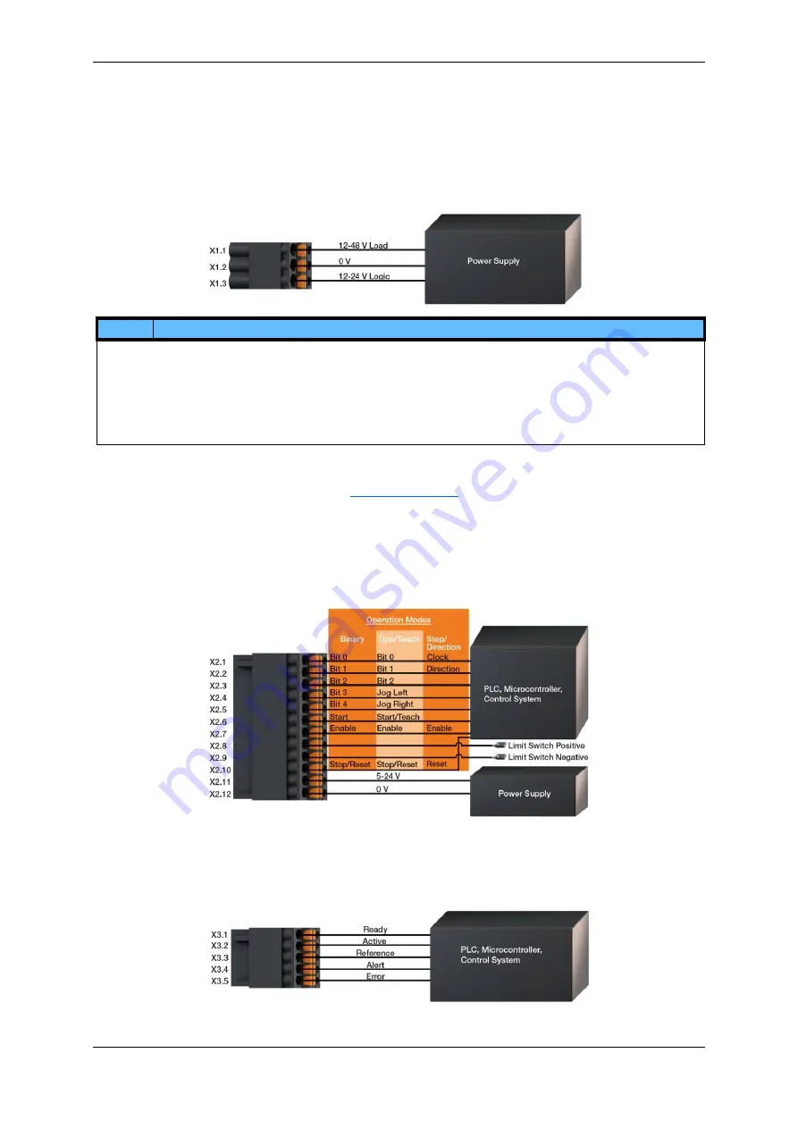
4.2.2 Pin Assignment
The connectors must be wired according to your application. For this purpose, use the detailed illustrations below for each
individual connector.
X1 Logic/Load Connector
If the dryve D1 is to be connected as a PELV wiring, the 0 V X1.2 terminal is to be connected to the earth potential of the overall
application.
NOTE
If the load voltage supply to connector X1.1 is cut off the motor will stop an uncontrolled way and the controller will emit error
“E08 Load Supply Low”. This error must be reset after the load voltage supply is on again.
In the case that an emergency stop must be executed it is recommended to disable the controller via the Digital Input DI 7
“Enable”. Thereby a “Quick Stop” with a defined deceleration will be executed.
Whi
le decelerating a “Following Error” might occur if the application is not set up correctly or unforeseen forces are applied to
the motor. In such an e
vent the controller will stop, emit the error “E11 Following Error” and the motor will stop an
uncontrolled way. This error needs a reset as well
X2 Digital Inputs Connector
The wiring and function of each input depends on the
To enable an operation of the dryve D1 motor control system, a voltage supply for the digital inputs must be connected to X2.11
and X2.12 (5-24 V). The same voltage source as that of the logic supply at X1.3 applicable. A connected PLC or microcontroller
must be attached to the same electric potential as the dryve D1 to maintain a proper operation,
All inputs must be uniformly wired as either PNP or NPN. The type of wiring interconnection can be selected later via the user
interface.
The Digital Inputs can be configured in such a way that they are activated in response to a high or low signal (NO contacts/NC
contacts).
X3 Digital Outputs Connector
The output voltage of the digital outputs corresponds to the voltage across the X2.11 connector.
The outputs have been permanently set to PNP and cannot be changed to NPN. Due to the internally installed pull-down
resistors, micro-controllers that work with NPN logic can be used as well. The digital outputs can be configured in such a way
that the emitted signals are inverted.


