background image

C H A N N E L S   F A C T O R Y   D E F A U L T   S E T T I N G  


28 

MRBP.424321.001G2 Version 1.0 15/06/2020


7


CHANNELS FACTORY DEFAULT SETTINGS 

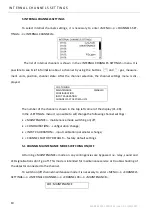
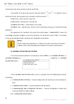
To  set  factory  default  for  all  the  channels  it  is  necessary  to  enter 

«

MENU

»


→  «

CHANNELS 

SETTINGS

» → «

CHANNELS FACTORY SETTINGS

».


CHANNELS 

FACTORY 

SET-

TINGS 

INTERNAL CHANNELS 
EXTERNAL CHANNELS 


In the 

«

CHANNELS FACTORY DEFAULT

» 

menu it is possible to select channels group for fac-

tory default settings. 

7.1


INTERNAL CHANNELS FACTORY DEFAULT SETTINGS 

To  set  all  channels  factory  default  it  is  necessary  to  enter 

«

MENU

»  →  «

CHANNELS  SET-

TINGS

» → «

CHANNELS FACTORY DEFAULT

» → «

INTERNAL CHANNELS

»

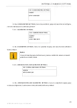
INT. CHANNELS FACTORY SETTINGS 

CONFIGURATION SETTINGS 
CALIBRATION SETTINGS 
CONFIG. AND CALIB. SETTINGS 


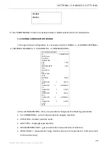
In  the 

«

INTERNAL  CHANNELS  FACTORY  DEFAULT

» 

menu  it  is  possible  to  set  the  following 

channels factory default: 


«

CONFIGURATION  SETTINGS

» 

-  configuration  and  channels  maintenance  mode  factory 

default; 


«CALIBRATION SETTINGS» 

- channels calibration factory default; 


«CONFIGURATION AND CALIBRATION SETTINGS» 

- configuration, maintenance mode and 

calibration factory default. 

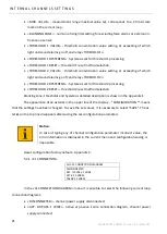
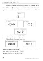
7.1.1


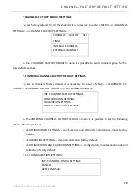
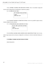
«

CONFIGURATION SETTINGS

» 


INT. CHANNELS CONFIG. SETTINGS 

CANCEL 
APPLY AND SAVE 


Summary of Contents for EMI-SSD-1M

Page 1: ...r Address 27 Engels Prospect building 5 litera A Saint Petersburg 194156 Russia Tel 8 800 234 66 90 Website www igm pribor ru E mail support igm pribor ru EMI SSD 1M TUNING GUIDE MRBP 424321 001G2 Sai...

Page 2: ...5 4 4 ACCESS SETTINGS 16 4 5 CONTINGENCIES ARCHIVE CLEARING 18 4 6 DEFAULT SETTINGS 18 5 INTERNAL CHANNELS SETTINGS 19 5 1 CHANNEL MAINTENANCE MODE TURNING ON OFF 19 5 2 CHANNEL CONFIGURATION CHANGE 2...

Page 3: ...structure 36 Appendix B Factory default parameters 40 Appendix C Gases configuration factory settings parameters 41 Appendix D Operation modes contingencies signaling and relay actuation description...

Page 4: ...anuals Only persons with at least the third electrical safety access qualification level having the cer tificate for work on electrical installations up to 1000 V and trained in workplace safety are a...

Page 5: ...ttings complete list can be found in the guide sections SETTINGS INTERNAL CHANNELS SETTINGS EXTERNAL CHANNELS SETTINGS ARCHIVING MODE SETTINGS At the first start default settings and methane channels...

Page 6: ...Channel initialization mean time is no longer than 130 seconds after that main operation mode is displayed 1 3 CHANNELS REBOOT To reboot internal channels or one of internal channels it is necessary...

Page 7: ...ayed WORK COMPLETION REBOOT POWER OFF After menu REBOOT selection the following message is displayed WORK COMPLETION CONTROLLER REBOOT This message means reboot is in Reboot mean time is 3 5 s after w...

Page 8: ...8 MRBP 424321 001G2 Version 1 0 15 06 2020 After menu POWER OFF selection turning off window is displayed Power off mean time is 3 5 s after which the control unit display blinks off and sensors pow...

Page 9: ...el settings Current time New contingency icon disappears after new record review in the contingencies menu Data exchange with the control unit via RS 485 icon disappears in 5 seconds after data exchan...

Page 10: ...AUTO THRESHOLD 2 RESET AUTO CL CONNECTION PASS 2wires CURRENT mA 4 000 In the top left corner is the channel number and sensor item tag hereunder is the present channel information To return to the ma...

Page 11: ...ngencies summary for the controller REBOOT controller EMI SSD 1M reboot by the user TURN OFF EMI SSD 1M control unit turn off by the user TURN ON EMI SSD 1M control unit turn on CONTINGENCIES ARCHIVE...

Page 12: ...DISPLAY 12 MRBP 424321 001G2 Version 1 0 15 06 2020 MEASUREMENT RANGE EXCEEDED measurement range exceeded CL SHORT CIRCUIT channel current loop short circuit Contingencies more detailed description i...

Page 13: ...OMMUNICATION communication parameters selection DISPLAY display parameters selection ACCESS access settings CONTINGENCIES ARCHIVE CLEARING contingencies archive clearing DEFAULT SETTINGS factory defau...

Page 14: ...of the display COMMUNICATION means that the values of the network address and or rate have been changed To apply and save the set values it is necessary to select SAVE The asterisk on the top line di...

Page 15: ...yed channel in the main operation mode auto change time interval set BRIGHTNESS display brightness settings The appearance of an asterisk in the upper line of the display DISPLAY means that the settin...

Page 16: ...using the buttons and 4 3 1 BRIGHTNESS Display brightness change from 1 to 100 Edited category is chosen by using the buttons and The parameter is changed by using the buttons and 4 4 ACCESS SETTINGS...

Page 17: ...d Value is changed by using the buttons and To apply and save the password it is necessary to select SAVE and push the button After successful saving of the new password the message is displayed CHANG...

Page 18: ...HIVE CLEARING CLEAR CONTINGENCIES ARCHIVE CANCEL CLEAR CONTINGENCIES ARCHIVE In the CONTINGENCIES ARCHIVE CLEARING it is possible to confirm or cancel contingen cies archive clearing 4 6 DEFAULT SETTI...

Page 19: ...ULTS The number of the channel is shown in the top left corner of the display C1 C8 In the SETTINGS menu it is possible to set change the following channel settings MAINTENANCE maintenance mode switch...

Page 20: ...UREMENT UNIT LFL MIN VALUE 0 0 MAX VALUE 100 0 BLANKING ZONE 1 0 THRESHOLD 1 VALUE 10 0 THRESHOLD 1 HYSTERESIS 0 0 THRESHOLD 1 RESET AUTO THRESHOLD 2 VALUE 20 0 THRESHOLD 2 HYSTERESIS 0 0 THRESHOLD 2...

Page 21: ...reset method selection Blanking zone thresholds and hysteresis detailed description is shown in the Appendix E The appearance of an asterisk in the upper line of the display CONFIGURATION means that t...

Page 22: ...rrectly Generally the channel switches to Detector breakout mode 5 2 2 POSITION Edited category is chosen by using the buttons and The category is changed by using the buttons and 5 2 3 GAS TYPE In th...

Page 23: ...hen in the ACCURACY menu select the appropriate one 5 2 5 MIN VALUE MAX VALUE BLANKING ZONE Edited category is chosen by using the buttons and The category is changed by using the buttons and 5 2 6 TH...

Page 24: ...e Manual threshold reset is carried out by using handshaking button Automatic reset is carried out after current concentration value decreasing below threshold level Notice If threshold is exceeded on...

Page 25: ...e top line disappears after saving the set configuration parameters Notice While analog input calibration it is necessary to select current loop connection method that is used hereinafter while detect...

Page 26: ...GS CANCEL APPLY APPLY AND SAVE In the CALIBRATION SETTINGS menu it is possible to apply and save channel calibration factory default Notice In case of selecting apply without save previous calibration...

Page 27: ...INTERNAL CHANNELS SETTINGS 27 MRBP 424321 001G2 Version 1 0 15 06 2020 6 EXTERNAL CHANNLES SETTINGS Under development...

Page 28: ...t all channels factory default it is necessary to enter MENU CHANNELS SET TINGS CHANNELS FACTORY DEFAULT INTERNAL CHANNELS INT CHANNELS FACTORY SETTINGS CONFIGURATION SETTINGS CALIBRATION SETTINGS CON...

Page 29: ...L APPLY AND SAVE In the INTERNAL CHANNELS CALIBRATION SETTINGS menu it is possible to apply and save channels calibration factory default 7 1 3 CONFIGURATION AND CALIBRATION SETTINGS INT CH CONF AND C...

Page 30: ...s and channel status archive record on SD card SD CARD INFORMATION storage capacity The appearance of an asterisk in the upper line of the display ARCHIVING SETTINGS means that the settings have been...

Page 31: ...TION SD CARD INFORMATION STATUS CONNECTED STORAGE CAPACITY 3049 Mb AVAILABLE MEMORY 1 Mb SD CARD INFORMATION menu is an informative SD card data window that contents STATUS SD card connection status S...

Page 32: ...TWARE VERSION 1 0 1 SOFTWARE DATE 01 01 2020 SOFTWARE TIME 12 00 00 OPERATION TIME d 1 Hh mm ss 02 05 00 In the DEVICE INFORMATION menu the following information is displayed SERIAL NUMBER controller...

Page 33: ...window is displayed Then program Loader menu is displayed where the following actions may be performed SOFTWARE UPDATING controller software version updating RESET TO FACTORY DEFAULT channels and cont...

Page 34: ...following message is displayed SOFTWARE FILES SD CARD NOT FOUND 10 2 CHANNELS AND CONTROLLER SETTINGS RESET TO FACTORY DEFAULTS To reset all control unit EMI SSD 1M settings to factory defaults it is...

Page 35: ...plete program Loader work it is necessary to press the button WORK COMPLETION QUIT THE LOADER REBOOT POWER OFF In the WORK COMPLETION menu it is possible to select one of the actions QUIT THE LOADER q...

Page 36: ...36 MRBP 424321 001G2 Version 1 0 15 06 2020 Appendix A EMI SSD 1M menu structure...

Page 37: ...37 MRBP 424321 001G2 Version 1 0 15 06 2020...

Page 38: ...38 MRBP 424321 001G2 Version 1 0 15 06 2020...

Page 39: ...39 MRBP 424321 001G2 Version 1 0 15 06 2020...

Page 40: ...off Internal channels settings Maintenance mode off CL connection type disconnected Position Gas methane Measurement units LFL Minimal concentration value 0 Maximal concentration value 100 Blanking z...

Page 41: ...e CH4 LFL 100 0 10 0 20 0 3 Propane C3H8 LFL 100 0 10 0 20 0 4 Carbon dioxide CO2 vol 2 50 1 00 2 00 5 Ethane C2H6 LFL 100 0 10 0 20 0 6 Butane 4 10 LFL 100 0 10 0 20 0 7 Isobutane i 4 10 LFL 100 0 10...

Page 42: ...n cyanide HCN ppm 30 0 1 9 9 9 33 Hydrogen H2 vol 2 00 0 10 0 40 34 Diesel fuel DT LFL 100 0 10 0 20 0 35 Methanol LOC 3 ppm 200 0 11 2 22 5 36 Hydrogen fluoride HF ppm 10 0 2 0 4 0 37 Hydrogen chlori...

Page 43: ...m 50 0 5 0 10 0 54 Carbonyl chloride COCl2 ppm 1 00 0 60 0 80 55 Methylmercaptan CH3SH ppm 10 0 4 0 8 0 56 Ozone O3 ppm 25 16 21 57 Bromine Br2 ppm 5 0 1 0 2 0 58 Formaldehyde CH2O ppm 10 0 1 0 2 0 59...

Page 44: ...off off NC NC NC No power supply or the device failed DISPLAY TURNED OFF no flashes every 1 s off NC NC NC Device turned off by the user no on off NC NC NO No tuned channels No power supply on pins X1...

Page 45: ...range ex ceeding no on off NC NC NO Channel maintenance mode enabled Short circuit in the channel supply circuit Channel power supply disconnected It is necessary to eliminate short circuit cause and...

Page 46: ...NC Current in the current loop circuit exceeds 31 mA It is necessary to eliminate short circuit in the current loop circuit cause after that the chan nel resumes work in main operation mode au tomatic...

Page 47: ...ormed automatically after measurand de creasing below thresholds 1 and 2 taking ac count of hysteresis In case of threshold 2 manual reset settings it is necessary to press the button constant frequen...

Page 48: ...e minimal value 0 blanking zone 5 On figure E 1 before the point 1 and after the point 2 value of the detector equal 0 set minimal value as they are below blanking zone value In the interval from the...

Page 49: ...Threshold 2 value hysteresis 2 value then relay Threshold 2 returns to initial condition common contact 2 closes to NC contact 3 Example threshold 1 value 10 hysteresis 1 value 3 On figure E 2 before...

Reviews: