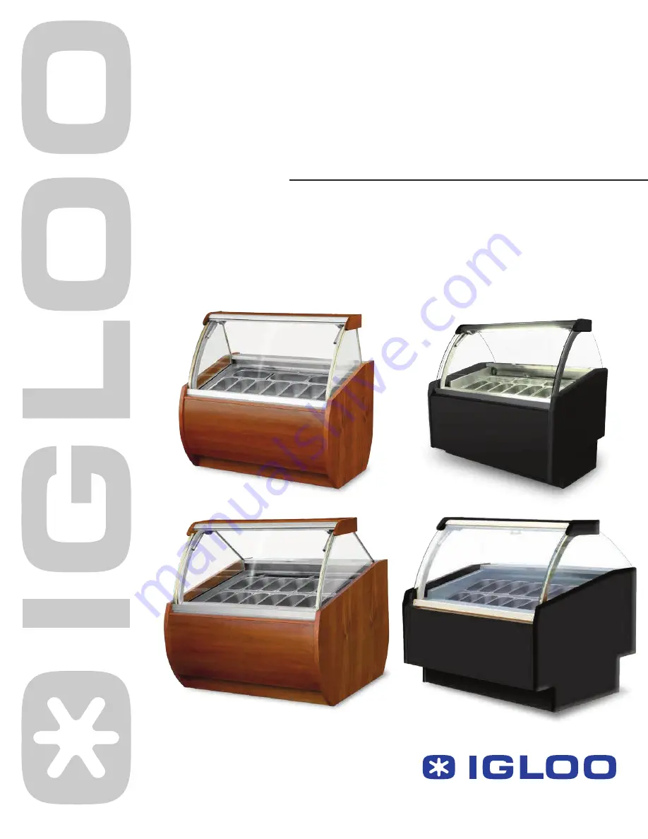
Ice Cream/ Gelato Cases
Models: ARBF & ARB2F series
ARBF
ARB2F
ARBTF
ARB2TF
Instruction Manual
Tel : 416-663-3051 Fax : 416-663-5793Toll Free : 1-888-408-8819
124 Norfinch Dr. Toronto, ON. M3N 1X1
REFRIGERATION LTD.
Page 1: ...Ice Cream Gelato Cases Models ARBF ARB2F series ARBF ARB2F ARBTF ARB2TF Instruction Manual Tel 416 663 3051 Fax 416 663 5793 Toll Free 1 888 408 8819 124 Norfinch Dr Toronto ON M3N 1X1 REFRIGERATION LTD ...
Page 2: ...ance 12 6 SERVICE 13 6 1 Faults identification and repair 13 6 2 Service 14 List of Figures Figure 1 ARBF ARB2F Overview 4 Figure 2 ARBF Layout of containers 4 Figure 3 ARB2F Layout of containers 4 Figure 4 Leveling legs 6 Figure 5 Install internal elements 7 Figure 6 Control panel 7 Figure 7 Front glass panel lifted improperly 8 Figure 8 Carel thermostat control panel 9 Figure 9 Cleaning the cond...
Page 3: ...pending on the environment of the unit location 2 2 Description of the unit ARBF and ARB2F display units have dynamic cooling The display cases are equipped with automatic defrosting and automatic condensate evaporation The electronic thermostat cooperate module to monitor and send signals when the temperature inside the equipment gets too low or too high The front glass can be listed with the tel...
Page 4: ...ling legs 5 Stainless steel work top 6 Stainless steel containers 7 Side glass 8 Serial plate 9 Control panel 10 Top shelf night curtain 11 Night curtain handle 12 Condenser cover DO NOT block the air louver ARBF4 _ 14 containers ARBF8 _ 28 containers ARB2F2 _ 7 containers ARB2F 3 _ 10 containers Figure 2 ARBF Layout of containers Figure 3 ARB2F Layout of containers ...
Page 5: ...5 3 PREPARING THE DEVICE FOR START UP The unit must be properly installed and located in accordance with the installation instructions before it is used 3 1 Installation requirements Always use a dedicated circuit with the amperage stated on the unit Plug into an outlet designed for the plug Do not overload the circuit Do not use extension cords Never use adapters Never plug in more than one unit ...
Page 6: ...f the unit display shelves front bumper To securely transport the equipment the unit may be shipped partially disassembled If the user received the unit partially disassembled perform the following operations 1 Place cross bars under stainless steel containers Figure 5 4 2 Place containers according to Figure 2 or Figure 3 3 Slide in glass sides according to Figure 5 2 The equipment should be clea...
Page 7: ... prevent problems with the start up WARNING Keep the cooling circuit away from damage Turn on the main switch Figure 6 2 The temperature on thermostat control panel PRE SET Figure 6 1 Turn on the light switch Figure 6 3 1 2 3 Figure 5 Install internal elements 1 Top shelf 2 Side glass 3 Container 4 Cross bar under containers 5 Wooden side Figure 6 Control panel 1 Thermostat temperature regulator p...
Page 8: ...noisy operation and will ensure proper water condensate outflow during defrosting After transporting the equipment wait about 2 hours before starting up The products should only be placed in the unit after it reached desired cooling temperature This principle should also be applied after long pause in operation Do not block any ventilation holes which would hamper circulation of the cooled air Do ...
Page 9: ...t working mode is activated Diode 2 Ventilator This symbol is visible when evaporator ventilators are turned on It blinks when the actuation of the ventilators is delayed by external disengagement or when another procedure is in progress Diode 3 Defrosting This symbol is visible when the defrosting function is activated It blinks when the actuation is delayed by external disengagement or when anot...
Page 10: ...g and holding the defrost switch for minimum 5 seconds Table 3 Table of alarms and signals alarm code buzzer and alarm relay LED alarm description reset E0 active ON probe 1 error control automatic E1 active ON probe 2 error defrost automatic E2 active ON probe 3 error condenser product automatic EE active ON unit parameter error not possible EF active ON operating parameter error manual Ed not ac...
Page 11: ...alue 10 C r1 99 r3 select direct reverse operation 0 0 2 r4 night time set point delta 3 0 C 50 50 c0 compressor and fan start delay on power up 1 min 0 100 c1 minimum time between consecutive compressor starts 2 min 0 100 c2 minimum compressor off time 0 min 0 100 c3 minimum compressor on time 1 min 0 100 c4 compressor on time with duty setting 50 min 0 100 cc continuous cycle duration 2 2 0 15 c...
Page 12: ...llage Do not use water stream to clean the equipment only a moist cloth Do not use any sharp objects to remove dirt It is recommended to make a break in the operation once a month in order to clean the interior naturally defrost the evaporator and clean the condenser Do not use mechanical agents to quicken the defrosting process A7 digital input alarm delay 0 min 0 199 A8 enable alarm Ed end defro...
Page 13: ... and maintenance To prevent damage Do not allow contact of the with substances containing chlorine and or baking soda in different varieties which destroy the protective layer and components of the equipment also includes various stainless steel 6 SERVICE 6 1 Faults identification and repair In case of any difficulties during actuation of the equipment or during its operation please return to the ...
Page 14: ...urniture adjoining the equipment does not vibrate when self contained compressor is working A noise made by the operating device is normal The units are equipped with ventilators engines and compressors which turn on and off automatically Each compressor makes certain noises when operating These sounds are made by the aggregate engine and by cooling agent flowing through the circuit This phenomeno...