P/N 1073220
• REV
C
• ISS
03JUL22
1
© 2021 Carrier. All rights reserved.
Specifications subject to change without prior notice
.
NS3503
-16P-4C-
V2 Quick Installation
Guide
Introduction
Thank you for purchasing IFS
L2/L4
Managed Gigabit
Ethernet Switch
. T
he description of this model is shown
below:
NS3503
-16P-4C-
V2
16-
port
10/100/1000T 802.3
bt PoE + 4
-
port
Gigabit TP/SFP Combo Managed Switch 16
-
port
“
Managed Switch
”
is used as an alternative name in
this
Quick Installation Guide.
Open the box of the Managed Switch and carefully
unpack it. The box should contain the items
l
isted below:
Package Contents
Model Series
NS3503
-16P-4C-
V2
Model Name
Package Item
NS3503
-16P
The Managed Switch
1
Quick Installation Guide
1
RS
-
232 to RJ45 Console Cable
1
Rubber Feet
4
Two Rack
-
mounting Brackets with
Attachment Screws
2
Power Cord
1
SFP Dust Caps
4
If any item is found missing or damaged, please contact
your local reseller for replacement.
Requirements
Workstations running Windows
XP
/2003/Vista/7/
8/2008/10
, MAC OS
X
or later,
Linux, UNIX,
or other platform
s are
compatible with
TCP/IP protocols.
Workstation
s are
installed with Ethernet NIC
(Network Interface Card)
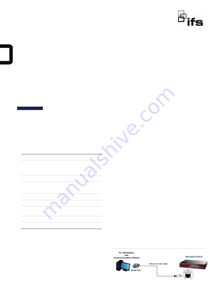
Serial Port Connection (Terminal)
The a
bove Workstations come
with COM Port
(DB9)
or USB
-
to
-
RS
-
232 converter
.
The a
bove Workstation
s ha
ve been
installed
with terminal emulator, such as
Hyper Terminal
included in Windows
XP/2003.
Serial cable
-- O
ne end
is
attach
ed
to the RS
-
232 serial port,
while
the other end to the
console port of the Managed Switch.
Ethernet Port Connection
Network cabl
es -- U
se standard network (UTP)
cables with RJ45 connectors.
The above
PC is
installed
with Web browser
and
JAVA runtime environment plug
-
in.
Note
: It is recommended to use Internet Explore
8
.0 or
above to access
the
Managed Switch. If the Web
interface
of the Managed Switch is not accessible,
please turn off the anti
-
virus software or firewall
and
then
try
it
again.
Terminal Setup
The
Managed Switch
is
equipped
with a console
interface for local switch setup and maintenance. To
configure the system, connect a serial cable to a
COM
port
on a PC or notebook computer and to
the
RJ45
type of the console port of the Managed Switch.
Figure 1: Managed Switch Console Connectivity


