Mechatronic flow sensor
SB1xxx SB2xxx SB3xxx SB4xxx SB5xxx SB6xxx SB7xxx SB8xxx SB9xxx
SB03xx
7
5 Mounting
CAUTION
During installation or in case of a fault (e.g. housing damage) media under high pressure or
hot media can leak from the system.
w
Risk of injury caused by pressure or burns.
u
Ensure that the system is free of pressure during installation.
u
Ensure that no media can leak at the mounting location during installation.
u
Equip the unit with suitable protection (e.g. cover) to avoid hazard to personnel from
leaking media.
5.1 Process connection
u
Avoid major changes of cross section on the inlet side. Use max. one connection size smaller.
u
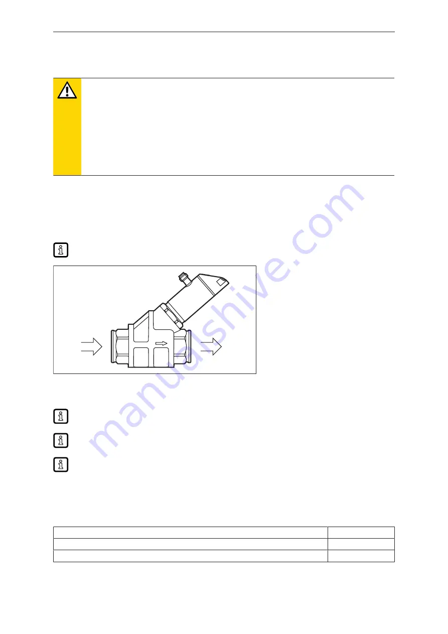
Fit the unit in the pipe in accordance with the flow direction (arrow) and tighten at the spanner flats.
Do not clamp the housing in a vice.
IN
OUT
Fig. 1: Process connection
IN:
inlet
OUT:
outlet
Calming sections on the sensor's inlet or outlet side are not necessary.
The sensor can also prevent backflow.
The sensor head can be rotated by 360°.
5.2 Interference
u
The following minimum distances must be adhered to:
Distance between the sensor and ferromagnetic materials
≥ 30 mm *
Distance between the sensor and constant / alternating fields
≥ 500 mm
Distance between the sensor axes for side-by-side installation
≥ 50 mm
* The pipe may consist of ferromagnetic material.


