Electronic level sensor
LW2120
19
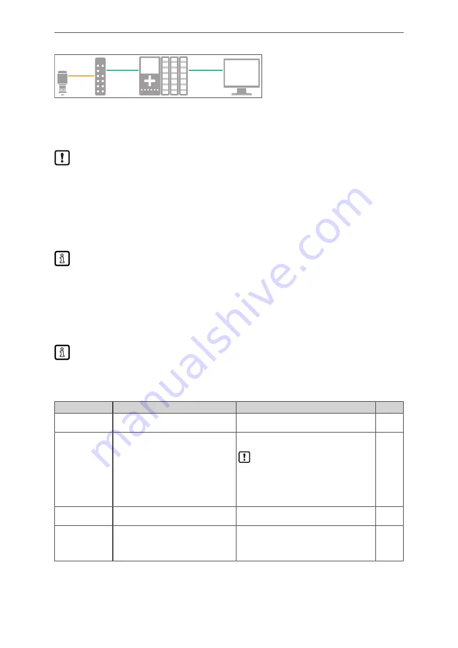
Fig. 14: Connection example with PLC
u
Read the unit using a suitable IO-Link software (
Ò
Observe the operating instructions of the
respective software).
u
Set the parameters.
Before parameter setting, familiarise yourself with all the parameters.
u
Check if the unit has accepted the parameter settings. If necessary, read the unit again.
u
Check whether the unit operates correctly.
6.3 Parameter setting via Bluetooth adapter
Using a Bluetooth adapter (
Ò
IO-Link accessory) facilitates parameter setting of the device, e.g.
for large containers or inaccessible mounting locations.
The possible parameter setting distance between the Bluetooth adapter and the device to be
paired depends on local conditions.
u
Using the Bluetooth adapter:
Ò
Bluetooth adapter operating instructions.
6.4 Adjustable parameters
Parameters marked with “!” (in the “Access” column) (e.g. [SSC1 Param. SP2]) are only active
after selection of the assigned parameters.
The abbreviations SSC1 and SSC2 below refer to the switching bits (switching signal channels) in the
IO-Link process data flow. The switching signal channels are assigned to the physical outputs OUT1
and OUT2 via the parameters [ou1] and [ou2].
Parameter
Options
Explanation
Access
uni
[m] = metre
[inch] = inch
Selection of the display unit.
Reference height
Setting range: 0.2...15 m
Distance between unit and zero point (
Ò
Fig.
Reference height).
The reference height defines the zero point. The
zero point might not necessarily correspond to
the tank bottom.
If necessary, set a tank offset (
Ò
Fig. Tank off-
set).
Tank offset
Setting range: -10...10 m
Distance between the zero point and the tank
bottom (
Ò
Fig. Tank offset).
Upper blind zone
Setting range: 0...10 m
Serves to suppress false echoes, e.g. from noz-
zles.
u
Check the echo peaks to detect the false
echoes near the tank’s upper edge.


