background image

CR720S CR721S

9

Connection

Nominal value fuse

Required triggering characteristics

VBB

15

2 A

T

fuse

 ≤ 120 s at max. 6.25 A

VBB

30

2 A

T

fuse

 ≤ 120 s at max. 6.25 A

VBB

0

15 A

-

VBB

1

≤ 15 A

-

VBB

2

≤ 15 A

-

VBB

3

≤ 15 A

-

VBB

4

 (only with CR721S)

≤ 15 A

-

VBB

5

 (only with CR721S)

≤ 15 A

-

Inputs / input groups

2 A

T

fuse

 ≤ 120 s at max. 6.25 A

All supply lines of the inputs can be protected within the input groups.

6.5 Laying of the supply and signal cables

supply

output

nn

output

nn

output

nn

controller

VBB

30

nn

VBB

15

nn

VBB

0

nn

VBB

1

nn

VBB

2

nn

VBB

3

nn

VBB

4

nn

VBB

5

nn

GND

SYS

nn

GND

1...4

GND

SYS

GND

RES

GND

ANA

GND

O

VA

GND

1...4

nn

input

nn

input

nn

GND

ANA

nn
nn

input

nn

sensor

sensor

sensor

load

load

load

GND

OVA

Shield

nn

nn

nn

nn

nn

nn

GND

RES

RESET-COM

1

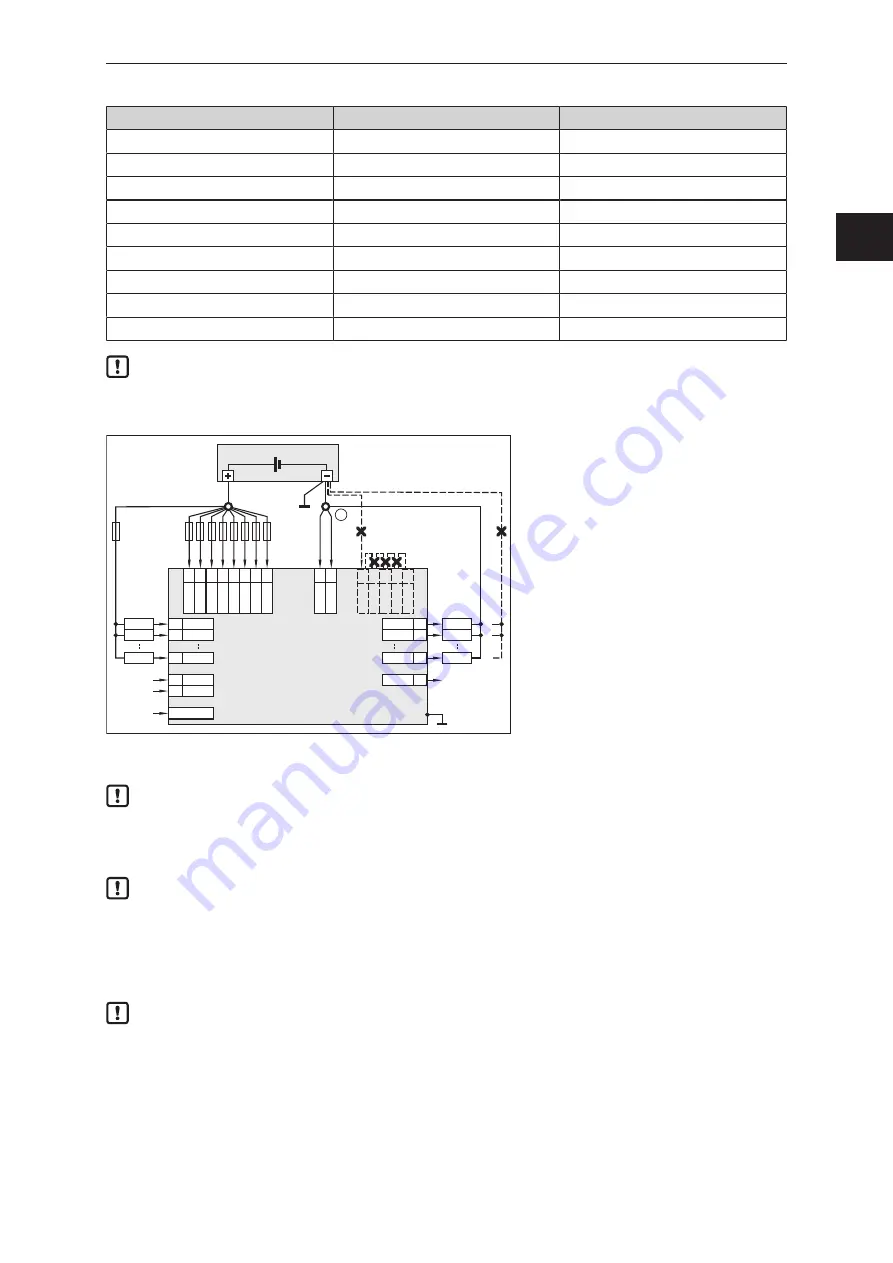
Fig. 4: Connection of the supply and signal cables (X = not permitted), example CR721S

1:

GND star point

Bridging of connections in the connectors is not permitted.

RESET-COM is a service input (see programming manual).

u

For the operation of the controller, connect RESET-COM to the GND star point 

.

Faulty laying of the supply and signal cables

w

Deterioration of EMC may occur

u

Lay all supply and signal cables separately to maintain application/EMC integrity

u

Connect supply and ground cables to the controller and the sensors/actuators via the
respective common star point.

If a prewired connection cable is used, remove the cores with unused signal inputs and outputs.

Provide the unconnected signal inputs with sealing of the individual cores. Unconnected cores or
core loops are not permitted.

In case of signal failures, operate inputs with shielded cables. Connect the shields to the shield
connection on one side.

GB

Summary of Contents for CR720S

Page 1: ...Original operating instructions ecomatController CR720S CR721S HW version V1 0 5 x 80299358 00 11 2020 GB...

Page 2: ...lectrical connection 7 6 1 Wiring 7 6 2 Connection technology 8 6 3 Shield connection 8 6 4 Fuses 8 6 5 Laying of the supply and signal cables 9 6 5 1 GND connections 10 6 6 Analogue inputs 10 6 7 Res...

Page 3: ...e safety of the system The system architect undertakes to perform a risk assessment and to create documentation in accordance with legal and normative requirements to be provided to the operator and u...

Page 4: ...r for mobile machinery applications Two separately programmable controllers safety PLC for safety related applications standard PLC for standard applications CODESYS V3 5 programming system in a versi...

Page 5: ...nstallation on the motor engine is not permitted No use in an environment with ionising radiation 4 Items supplied 1 ecomatController 1 screw for the shield connection 4 protective covers 1 original o...

Page 6: ...eeded w If housing temperatures presenting a danger to people are reached u Cover housing to prevent unintentional contact u Apply warning for hot surfaces visibly on the device 5 4 Installation posit...

Page 7: ...its 6 1 Wiring Wiring Technical data 16 The connection terminals may only be supplied with the signals indicated in the technical data on the device label and only the approved accessories from ifm ma...

Page 8: ...ngress resistance of cables that users have cut to length must be guaranteed u Use twisted pair cables for the CAN connection u For the Ethernet connection use a minimum category 5 Cat 5 cable The RS...

Page 9: ...ET COM 1 Fig 4 Connection of the supply and signal cables X not permitted example CR721S 1 GND star point Bridging of connections in the connectors is not permitted RESET COM is a service input see pr...

Page 10: ...ctuators loads to the common GND star point WARNING Wrong connection of the GND connections w Loss of the safety function the measurement accuracy and EMC possible u Do not connect the GNDANA GNDRES a...

Page 11: ...ot connect GNDANA to other GND connections or to the common GND star point 6 7 Resistor inputs supply controller VBB 30 nn VBB 15 nn VBB 0 nn VBB 1 nn VBB 2 nn VBB 3 nn VBB 4 nn VBB 5 nn GND SYS nn GN...

Page 12: ...6 9 Analogue outputs supply controller VBB 30 nn VBB 15 nn VBB 0 nn VBB 1 nn VBB 2 nn VBB 3 nn VBB 4 nn VBB 5 nn GND SYS nn GND 1 4 nn load A 0 10 V A 0 10 V GNDOVA Con B 52 GNDOVA Con A 33 32 51 Con...

Page 13: ...lt currents to flow through the controller and load which lead to an undefined state of the controller and the system w Loss of the safety function u Always connect the ground lead of the controller a...

Page 14: ...spective output Technical data u Supply low side outputs BL via a high side output BH of the same output group Deviating connections are not permitted 6 12 Mixed operation 12 V 24 V In case of supply...

Page 15: ...oftware and the CODESYS Safety SIL2 extension The people should also have knowledge of the following topics requirements on safety related programming required user specific standards 7 2 Required doc...

Page 16: ...or decentralised system design Mechanical data Housing closed screened metal housing with screw fixing Dimensions H x W x D 219 x 271 x 47 mm Installation fixing with 4 M6 screws Connection 2 x connec...

Page 17: ...e protocol CANopen Safety for safe data transmission Serial interface Baud rate Topology RS 232 9 6 115 2 kbit s default 115 2 kbit s point to point max 2 participants master slave connection Ethernet...

Page 18: ...ue on sleep mode SYS1 green on safe PLC no application 2 Hz run red 10 Hz error application serious error yellow 2 Hz debug run on debug stop ETH0 green flashing data transmission Ethernet on Ethernet...

Page 19: ...level IV function state A Pulse 3b severity level IV function state A Pulse 4 severity level IV function state A Pulse 5 severity level III function state A data valid for the 24 V system Pulse 4 sev...

Page 20: ...nge to detect short circuit to VBB and short circuit to GND wire break Multifunction inputs analogue digital IN MULTIFUNCTION A Current input 0 20 mA A Input resistance 298 Range diagnostics min max 0...

Page 21: ...Voltage input 0 10 V A Input resistance 67 6 k Range diagnostics min max 0 V 10 V default Accuracy 1 FS Digital input BL H default BL Input resistance 10 k Input frequency 330 Hz Switch on level 0 7 V...

Page 22: ...re break Digital inputs IN DIGITAL A Digital input BL Input resistance 10 k Switch on level 0 7 VBB30 Switch off level 0 3 VBB30 Accuracy BL 1 FS Range diagnostics min max 1 V 0 95 VBB30 default ST A...

Page 23: ...A and ST B input characteristics Control systems Abbreviations A BH BL FRQL H PWMH PWML PWMI R VBB0 3 VBB30 analogue binary high side CSO binary low side CSI frequency pulse inputs configurable low s...

Page 24: ...tput BL Functions as H bridge PWM output PWMH Output frequency 20 2000 Hz per channel Pulse pause ratio 1 1000 adjustable via software Resolution 1 at 20 250 Hz Range diagnostics min max 0 A 4 A defau...

Page 25: ...e 0 05 4 A Setting resolution 1 mA Control resolution 2 mA Load resistance 3 at 12 V DC 6 at 24 V DC Accuracy 1 5 FS for inductive loads Range diagnostics min max 0 A 4 A default ST A OUT0000 OUT0002...

Page 26: ...g voltage 8 32 V DC Switching current 0 025 2 5 A Protective circuit for inductive loads integrated Accuracy current feedback 5 FS Diagnostics current feedback configurable minimum and maximum values...

Page 27: ...ctor outputs each Forced controlling by means of hardware and additional controlling by means of user program Switching current 0 1 12 A Current diagnostics excessive current 12 A Short circuit streng...

Page 28: ...poles A coded 1 not used 2 not used 3 GND_COM 4 CAN0_H 5 CAN0_L CAN1 RS 232 M12 socket 5 poles A coded 1 RS 232_TxD 2 RS 232_RxD 3 GND_COM 4 CAN1_H 5 CAN1_L ETH0 ETH1 M12 socket 4 poles D coded 1 TxD...

Page 29: ...2 k 15 VBB 15 terminal 15 ignition GND Supply ST A L L L L L L L L L 22 OUT0006 PWMH L PWMI BH L 4 A H 23 OUT0007 PWMH L PWMI BH L 4 A H 12 OUT0106 PWMH L PWMI BH L 4 A H 13 OUT0107 PWMH L PWMI BH L 4...

Page 30: ...BL 10 k S 13 IN1203 BL 10 k S 40 IN1700 BL 10 k S S S 41 IN1701 BL 10 k 42 IN1702 BL 10 k 43 IN1703 BL 10 k S 25 IN1300 BL 3 2 k S 26 IN1301 BL 3 2 k S S S 27 IN1302 BL 3 2 k 28 IN1303 BL 3 2 k GND Su...

Page 31: ...sed system design Mechanical data Housing closed screened metal housing with screw fixing Dimensions H x W x D 219 x 271 x 47 mm Installation fixing with 4 M6 screws Connection 2 x connector 81 poles...

Page 32: ...ree protocol CANopen Safety for safe data transmission Serial interface Baud rate Topology RS 232 9 6 115 2 Kbit s default 115 2 Kbit s point to point max 2 participants master slave connection Ethern...

Page 33: ...on sleep mode SYS1 green on safe PLC no application 2 Hz run red 10 Hz error application serious error yellow 2 Hz debug run on debug stop ETH0 green flashing data transmission Ethernet on Ethernet c...

Page 34: ...y level IV function state A Pulse 3b severity level IV function state A Pulse 4 severity level IV function state A Pulse 5 severity level III function state A data valid for the 24 V system Pulse 4 se...

Page 35: ...e to detect short circuit to VBB and short circuit to GND wire break Multifunction inputs analogue digital IN MULTIFUNCTION A Current input 0 20 mA A Input resistance 298 Range diagnostics min max 0 m...

Page 36: ...s Voltage input 0 10 V A Input resistance 67 6 k Range diagnostics min max 0 V 10 V default Accuracy 1 FS Digital input BL H default BL Input resistance 10 k Input frequency 330 Hz Switch on level 0 7...

Page 37: ...to GND wire break Digital inputs IN DIGITAL A Digital input BL Input resistance 10 k Switch on level 0 7 VBB30 Switch off level 0 3 VBB30 Accuracy BL 1 FS Range diagnostics min max 1 V 0 95 VBB30 def...

Page 38: ...ST A and ST B input characteristics Control systems Abbreviations A BH BL FRQL H PWMH PWML PWMI R VBB0 5 VBB30 analogue binary high side CSO binary low side CSI frequency pulse inputs configurable low...

Page 39: ...ND according to programming manual detection TRUE 3 V detection FALSE 1 V Digital PWM outputs 4 0 A H bridge OUT PWM 40 BRIDGE A Digital output BH default Switching voltage 8 32 V DC Range diagnostics...

Page 40: ...to detect short circuit and wire break Diagnostics status feedback detection of short circuit to VBB and short circuit to GND detection TRUE 3 V detection FALSE 1 V Digital PWM outputs 4 0 A OUT PWM 4...

Page 41: ...software Resolution 1 at 20 250 Hz Range diagnostics min max 0 A 2 5 A default Current controlled output PWMI Output frequency 20 2000 Hz per channel Control range 0 05 2 5 A Setting resolution 1 mA...

Page 42: ...Step response time 10 90 1 8 ms Analogue outputs OUT VOLTAGE A Output groups VBB0 5 Load current per output group 12 A Internal semiconductor switches One switch in series of 9 semiconductor outputs e...

Page 43: ...les A coded 1 not used 2 not used 3 GND_COM 4 CAN0_H 5 CAN0_L CAN1 RS 232 M12 socket 5 poles A coded 1 RS 232_TxD 2 RS 232_RxD 3 GND_COM 4 CAN1_H 5 CAN1_L ETH0 ETH1 M12 socket 4 poles D coded 1 TxD 2...

Page 44: ...3 2 k 15 VBB 15 terminal 15 ignition GND Supply ST A L L L L L L L L L 22 OUT0006 PWMH L PWMI BH L 4 A H 23 OUT0007 PWMH L PWMI BH L 4 A H 12 OUT0106 PWMH L PWMI BH L 4 A H 13 OUT0107 PWMH L PWMI BH L...

Page 45: ...28 IN1303 BL 3 2 k GND Supply 03 VBB 4 04 VBB 3 ST B L L L L L L L L L 22 OUT0306 23 OUT0307 69 OUT0406 70 OUT0407 79 OUT0506 24 OUT0308 71 OUT0408 81 OUT0508 16 OUT0300 18 OUT0302 20 OUT0304 63 OUT04...

Reviews: