


IO-Link master
24
15.5 Connection notes
Implement the FE connection using mounting screws, in order to ensure immunity to interference�
To ensure IP 65/IP 67 protection, cover unused sockets with protective caps�
Only supply the IO-Link master and the IO-Link devices with the voltage U
S
und U
A
provided at the
terminal points�
Observe the correct polarity of the supply voltages US and UA in order to prevent damage to the
device�
When connecting the sensors and actuators, observe the assignment of the connections�
Secure the device to a level surface or to a profile� Do not use this device to bridge gaps, in order to
prevent forces being transmitted via the device�
Use standard M5 screws with toothed lock washer and self-locking nuts� Observe the maximum
torque of the screws�
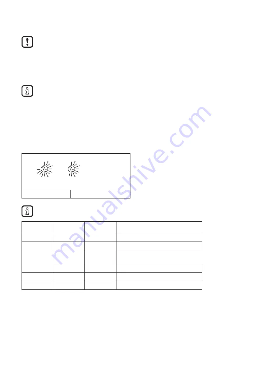
16 Configuration via rotary encoding switch
You can configure the address assignment and other functions using rotary
encoding switches�
0
2
4
6
8
10
12
x10
S1
0
2
4
6
8
x1
S2
9
S1 (x10)
S2 (x1)
►
After modifying the switch position, restart the device� A modification to the switch position does
not take effect during operation�
S1
S2
Code
Function
0
0
00
Reserved
0 ��� 12
1 ��� 5
01 ��� 125
Manual address assignment
12
6
126
Setting the slave address (set slave
address command)
12
7
127
Reserved
12
8
128
Reserved
12
9
129
Reserved