background image

Print More Materials, All For Application

- 32 -

6.

Maintenance and Care

This equipment belongs to high temperature equipment, the internal use environment

temperature is high, do not replace the conventional parts to avoid machine failure. Please deal with

the problem under the guidance of professionals.

6.1 Maintenance of Linear Guide and Ball Screw

Ball screw and linear guide are the guarantee to keep secure operation, and the correct

maintenance can effectively increase the service life of the machine. It is recommended to add

lubricating oil once every half month if it is used for a long time,

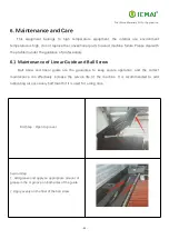
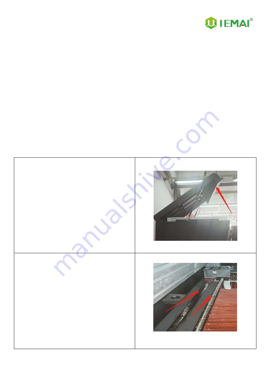
First Step:Open top cover

Second step:
1. Add grease and apply an appropriate amount of
grease in the V-groove on both sides of the guide.

2. Apply evenly on the fillet of the ball screw.

Summary of Contents for HIGH-TEMPERATURE Series

Page 1: ...GIC HT MAX Operating Instructions www iemai3d com Please read this manual carefully before starting to operate This device is a Class A product Use in a general indoor environment may cause radio interference and therefore requires the user to take appropriate protective measures ...

Page 2: ...ore Materials All For Application 2 The contents of this operating instructions may be updated periodically Scan the QR code or visit the link below to get the latest version www iemai3d com index php download ...

Page 3: ... Unload Filament 24 4 3 Start Printing 26 4 4 Disassembly Model 27 4 5 PEEK Material Printing Precautions 27 4 6 PC Based WIFI LAN control 28 5 Function Introduction 29 5 1 Power Failure Recovery 29 5 2 Filament Absent Warning 29 5 3 Chamber Temperature Setting 30 5 4 Moisture Proof Cabinet Setting 31 6 Maintenance and Care 32 6 1 Maintenance of Linear Guide and Ball Screw 32 6 2 Dust Removal from...

Page 4: ...SU PEI 1010 9085 and other high performance materials nylon PC ABS PETG ASA TPU PLA and other general engineering materials and composite reinforcement materials of the above materials carbon fiber glass fiber flame retardant anti static etc The MAGIC HT MAX comes with individual lifting dual print head that supports the printing of support materials including water soluble PVA limonene soluble HI...

Page 5: ...ose the high quality filament provided by other regular filament manufacturers and users should be responsible for the loss caused by using low quality filament Please keep the consumables sealed and moisture proof if not in use for a long time please bake and dry them in advance before using them again Software Please use a 64 bit system with Windows 7 or above to run the software more than 4G of...

Page 6: ...h The maximum temperature of the printing platform of this equipment can reach 200 C its heating is strictly prohibited to touch The maximum temperature of the chamber of this equipment can reach 150 C and it is strictly forbidden to touch it when it is heated Ensure that the power supply grounding terminal is well grounded to prevent the printer from not working properly or posing a risk of elect...

Page 7: ...Print More Materials All For Application 7 2 Detailed Parameter 2 1 Specification ...

Page 8: ...Print More Materials All For Application 8 ...

Page 9: ...or Application 9 2 2 Device Layout Filament Box Emergency Stop 7 Inch Touch Screen Chamber Temperature Controller Main Electric Box Date Transfer Area Vacuum Pump Box Moisture Proof Storage Material Box Door Front Door Top Cover ...

Page 10: ...Print More Materials All For Application 10 Internal Chamber ...

Page 11: ...Print More Materials All For Application 11 Filament Box Electric Box Pressure Gauge Air Pump Cooling Fan ...

Page 12: ...Print More Materials All For Application 12 Cooling Fan Built In Light Built In Camera Motor Power Outlet ...

Page 13: ...3 2 3 Interactive Interface The interactive interface of the device adopts a 7 inch Chinese English color touch screen resistive Please read the following interface instructions carefully before first use Logic diagram of interactive interface ...

Page 14: ...original factory settings 5 Tap TPAAdjustment to correct the touch offset 6 Click WIFI to go to Figure 5 Figure 3 Info interface 1 This interface allows you to view the current coordinates of the XYZ axis 2 The current temperature of the left nozzle and right nozzle and hot bed Figure 4 About interface This interface allows you to view the name ID system version UI version and Power On Off sounds ...

Page 15: ...information Figure 3 Manual Here can do the following 1 Select the moving unit of 0 1 10mm 2 Controls the XYZ axis for unit movement 3 Click to go back to the original point 4 Select E1 or E2 for unit extrusion Figure 4 Pre Heat interface 1 This interface allows you to set the preheat temperature of the hot bed left nozzle and Right nozzle Figure 5 Filament interface 1 Loading material 2 Unload ma...

Page 16: ...ce in print You can view thumbnails 2 Hot bed Nozzle Temperature and chamber temperature 3 Elapsed time Time remaining Current speed 4 File name Print Progress Bar 5 You can control pause resume and stop printing 6 Press to Figure 4 Figure 4 Print Setting Interface 1 This interface can be adjusted during the printing process 2 Print Speed Ratio Temperature of Hot Bed Nozzle 3 Fan Rate of E1 E2 and...

Page 17: ...mage please refuse to receive Step 2 1 The equipment is tightly packed and protected 2 Please be patient in removing the package 3 If you need to use tools such as knives scissors 4 Please be cautioned to avoid scratching the device Step 3 Check whether the door glass and control panel are in good condition Step 4 Note The starter kit and material pack are placed in the material box on the right ...

Page 18: ...ves normally Step 5 1 Control E1 and E2 extrusion through the touch screen 2 Check whether the gears of the left and right sprinklers rotate clockwise Step 6 1 Preheat through touch screen 2 It can set the temperature of hot bed left nozzle and right nozzle 3 The temperature on the right represents the set temperature and the temperature on the left represents the actual temperature 4 Recommended ...

Page 19: ...int More Materials All For Application 19 4 Print Operation 4 1 Install Print Platform And Leveling Step 1 Install sealing strips Step 2 Install carbon fiber plate Step 3 Turn on the vacuum suction switch ...

Page 20: ...et to zero otherwise there is a risk that the platform will hit the nozzle resulting in machine failure During the self test the self test will be performed twice If there is no action manually pull out the probe and start the self test again Step 2 After passing the self test click return to zero Step 3 The X axis transverse Y axis vertical is zeroed in turn and finally the Z axis is raised and z...

Page 21: ...d stop the machine Step 6 The mode setting is as follows 1 After returning to zero use a working range of 0 1mm to control the upward movement of the Z axis and observe that the nozzle stops moving when it touches the platform 2 Disconnect the plug of the emergency stop limiter and test the black and white interfaces using a multimeter Adjust the multimeter to the buzzer setting at this time there...

Page 22: ... unplug the limit connector and open the right electric box cover find the leakage protector and press the gray button switch up to start the machine After starting drop the Z axis and connect the connector of the emergency stop limiter Adjust the height of the emergency stop limiter according to the situation If the limiter is triggered in advance resulting in a shutdown you can adjust the limite...

Page 23: ...onnect Z limit cable must be used with firmware changes Step 2 1 Using the working range of 0 1mm and 10mm so that the printing platform is just a fixed height from the nozzle 2 The print head is manually controlled to move to various positions on the platform Step 3 The height of the platform is adjusted point by point in a clockwise way The adjusting screw can be turned clockwise to reduce the h...

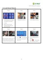
Page 24: ...rature of different materials Step 2 Straighten the material Step 3 Cut the material to the tip Step 4 When loading the material press the distal extrusion clip and insert the material until the material can not go in Step 5 1 Click to load materials 2 E1 for the left nozzle E2 for the right nozzle Step 6 1 Till the nozzle appears fine filament 2 Click Stop loading and unloading command ...

Page 25: ... the material is out of the gear pull it out manually and fix the thread keep it well against moisture Step10 Recommended preheating nozzle temperature for commonly used materials Special Engineering Plastics PEEK 430 PEKK 430 PEI 1010 360 PEI 9085 360 PPSU 360 PPS 300 Reinforced Composites Material CF PEEK GF PEEK 450 CF PEKK ESD PEKK 430 GF PA CF PA 300 CF PC PC FR PC ABS 270 CF ABS 260 ESD PETG...

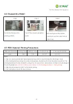
Page 26: ...art Printing Step 1 In the IEMAI slicing software the code will be saved to the SD card please see the software tutorial for detailed slicing methods Step 2 Insert the USB into the USB port and select the slice file Step 3 Click ready to start printing ...

Page 27: ...xis support spacing peek 400 100 90 120 0 15 0 2 Note 1 Peek can only be printed with high temperature head Brim is recommended for attachment mode 2 When heating before printing the constant temperature chamber and hot bed should be heated first The printing head should not be heated for a long time It is easy to form carbonization and lead to the blockage of the printing head see common problems...

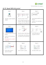
Page 28: ...y the generated file to the SD card 2 and put it on the machine to print once Step 4 1 Copy the generated file to the SD card 2 and put it on the machine to print once 3 0 0 0 0 means not connected successfully Step 5 1 Enter the software and click Scan 2 Automatically reads machines in the network and connects them Step 6 1 Green status indicates successful connection Step 7 1 Preheat and movemen...

Page 29: ...xis of the printer has not moved after power failure otherwise it will not be able to continue printing after the last breakpoint 5 2 Filament Absent Warning Step 1 If the printer runs out of material during printing please select Yes in this screen to load material Step 2 1 Unloading materials 2 Loading materials 3 E1 for left E2 for right 4 Unload the existing material first and then load materi...

Page 30: ... key to enter the setting interface Step 3 1 Through transposition keys increase decrease keys 2 Set target temperature 3 This is the left and right temperature setting at the same time Step 4 1 Press and hold the set button 2 When the target temperature window number stops jumping Release the button Step 5 Output control indicators OUT1 and OUT3 are on and the temperature rises ...

Page 31: ... Target humidity value jump Step 3 1 Use the increase decrease keys 2 Set the specified target humidity 3 Recommended setting is a minimum of 10 RH Step 4 1 Click on the settings to return to the status display screen Step 5 1 Fan rotation indicates that the device is working Step 6 1 Status during long operation 2 The display will be in a sleep state 3 Can use start up display ...

Page 32: ...essionals 6 1 Maintenance of Linear Guide and Ball Screw Ball screw and linear guide are the guarantee to keep secure operation and the correct maintenance can effectively increase the service life of the machine It is recommended to add lubricating oil once every half month if it is used for a long time First Step Open top cover Second step 1 Add grease and apply an appropriate amount of grease i...

Page 33: ...he motherboard and prevent the drive from overheating and out of step phenomenon Step two Remove the dust cover Insert and gently pull out the dust cover from the four corners of the dust cover Step three Remove dust from the dust cover and fans Use an air gun to remove the dust from the sponge in the dust cover and blow clean the fan note that the pressure should not be too high when blowing the ...

Page 34: ...zle is high temperature and the operation should be careful of scalding 2 Replacement perform the second and fourth steps for high temperature printing head Step 1 Normal temperature print head will heat up the nozzle about 150 Step 2 Remove the quick detachable head hold the heating block with pliers and remove the nozzle counterclockwise with sleeve Step 3 Take out a new nozzle and wrap the thre...

Page 35: ...heet to shade the inner sensor Print head switch to print head 2 Step 3 Move the X axis left negative limit by 20mm Head 2 is just stay in the postion where head 1 was tested previously Step 3 Turn the adjusting screw above the left nozzle clockwise to raise No 2 head By adjusting the No 1 head and the platform at the same height Note When adjusting the nozzle height the same point on the platform...

Page 36: ...ve to the positive direction of the Y axis decrease Y axis spacing negative Step 3 1 Open the slicing software 2 Adjust the parameters in the print head settings 3 Make up the difference according to the gap produced by printing 4 Difference between the right printhead and the left printhead Step 4 1 Print the two color miniature again 2 According to the printing effect to the left nozzle as the s...

Page 37: ... them first refer to Printing Loading and Unloading materials for details and pull out the feed pipe Step 2 Turn off the power and loosen the three screws as shown in the picture Step 3 Pull out the print head to complete the removal To replace a new print head the procedure is as follows Step 1 Load the removed print head into the original position and tighten the three removed screws as shown in...

Page 38: ...u click to move Check if the limit switch is pressed Problem 3 Opposite direction of motion Open the firmware and change the control code 1 or 1 Problem 4 When the machine is running the power is off with a bump sound and the machine does not respond when it is turned on again Refer to 4 1 2 Use Automatic leveling to print 8th 7 2 Temperature Problem Solution Problem 1 Click heating the temperatur...

Page 39: ...he print appears to be detached from the bottom and is carried away After determining that the platform is able to print that material adjust the platform and nozzle gap when the zero point is small see Printing Installing the Build Platform and Leveling for more information Problem 3 Dual head printing does not work well together Refer to the maintenance nozzle spacing adjustment ...

Page 40: ...and slowly pull out the needle Filament will out of the nozzle with the needle If the blockage is serious it is recommended to clear with a drill Treatment method 2 1 Remove the printing head according to the printing head disassembly and maintenance 2 Loosen the screws as shown in the figure and remove the pipe heater block and nozzle 3 Use 1 95mm drill bit complimentary to drill out the material...

Page 41: ...gh and low temperature of the print head Note High temperature nozzle is suitable for printing materials with temperature over 300 Normal temperature nozzle is suitable for printing materials with temperatures below 300 and is not interchangeable Normal Temperature High Temperature ...

Page 42: ...before leaving the printer Observe the molding effect of the side skirt to determine whether the height between the nozzle and the platform is appropriate As in the case of Figure 1 The skirt line is loose and independent and separated by one root This means that the nozzle is a little far from the platform you can increase the automatic leveling compensation parameters to make the nozzle and plat...

Reviews: