WSB-H610 PICMG 1.0 CPU Card
Page 35
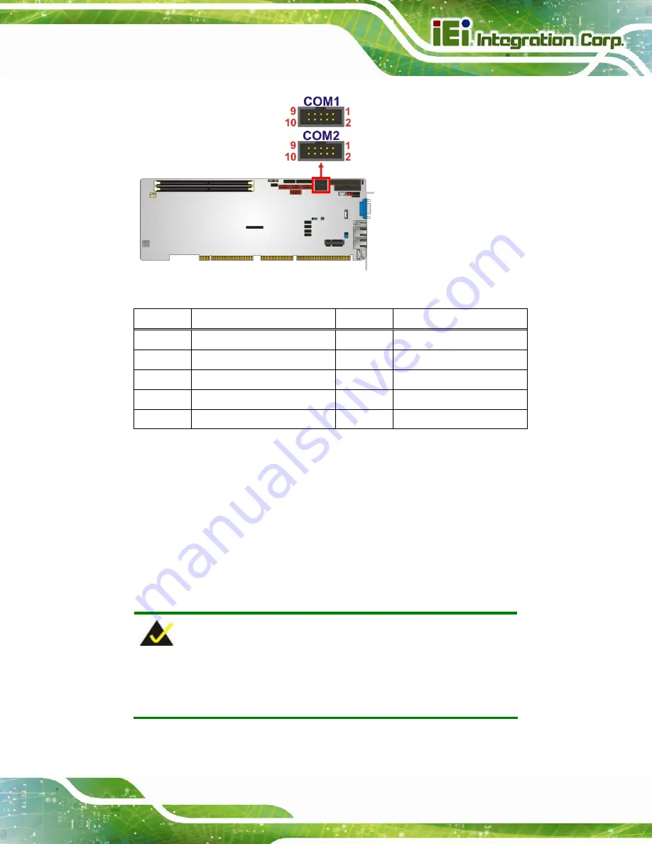
Figure 3-19: Serial Port Connector Location
Pin
Description
Pin
Description
1
DATA CARRIER DETECT (DCD) 2
DATA SET READY (DSR)
3
RECEIVE DATA (RXD)
4
REQUEST TO SEND (RTS)
5
TRANSMIT DATA (TXD)
6
CLEAR TO SEND (CTS)
7
DATA TERMINAL READY (DTR)
8
RING INDICATOR (RI)
9
GND
10
GND
Table 3-19: Serial Port Connector Pinouts
3.2.19 Serial Port Connector, RS-422/485
CN Label:
COM3
CN Type:
4-pin wafer
CN Location:
CN Pinouts:
NOTE:
These pins are shared with those on the main serial port. Use either
the pins on the main connector, or on this connector, but not both.
This connector provides RS-422 or RS-485 communications.
Summary of Contents for WSB-H610-R11
Page 15: ...WSB H610 PICMG 1 0 CPU Card Page 1 Chapter 1 1 Introduction...
Page 20: ...WSB H610 PICMG 1 0 CPU Card Page 6 Figure 1 4 External Interface Panel Dimensions mm...
Page 24: ...WSB H610 PICMG 1 0 CPU Card Page 10 Chapter 2 2 Packing List...
Page 30: ...WSB H610 PICMG 1 0 CPU Card Page 16 Chapter 3 3 Connectors...
Page 58: ...WSB H610 PICMG 1 0 CPU Card Page 44 Chapter 4 4 Installation...
Page 79: ...WSB H610 PICMG 1 0 CPU Card Page 65 Chapter 5 5 BIOS...
Page 115: ...WSB H610 PICMG 1 0 CPU Card Page 101 6 Software Drivers Chapter 6...
Page 128: ...WSB H610 PICMG 1 0 CPU Card Page 114 Appendix A A Regulatory Compliance...
Page 130: ...WSB H610 PICMG 1 0 CPU Card Page 116 Appendix B B BIOS Options...
Page 133: ...WSB H610 PICMG 1 0 CPU Card Page 119 Appendix C C Terminology...
Page 137: ...WSB H610 PICMG 1 0 CPU Card Page 123 Appendix D D Digital I O Interface...
Page 140: ...WSB H610 PICMG 1 0 CPU Card Page 126 Appendix E E Watchdog Timer...
Page 143: ...WSB H610 PICMG 1 0 CPU Card Page 129 Appendix F F Hazardous Materials Disclosure...


