


WAFER-PV-D5252/D4252/N4552 SBC
Page 51
4.6 Chassis Installation
4.6.1 Airflow
WARNING:
Airflow is critical for keeping components within recommended
operating termperatures. The chassis should have fans and vents as
necessary to keep things cool.
The WAFER-PV-D5252/D4252/N4552 must be installed in a chassis with ventilation holes
on the sides allowing airflow to travel through the heat sink surface. In a system with an
individual power supply unit, the cooling fan of a power supply can also help generate
airflow through the board surface.
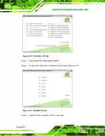
4.6.2 Motherboard Installation
To install the WAFER-PV-D5252/D4252/N4552 motherboard into the chassis please refer
to the reference material that came with the chassis.
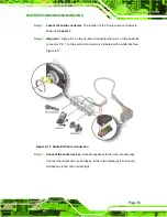
4.7 Internal Peripheral Device Connections
This section outlines the installation of peripheral devices to the onboard connectors.
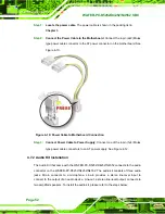
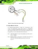
4.7.1 AT Power Connection
Follow the instructions below to connect the WAFER-PV-D5252/D4252/N4552 to an AT
power supply.
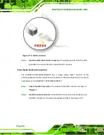
WARNING:
Disconnect the power supply power cord from its AC power source to
prevent a sudden power surge to the
WAFER-PV-D5252/D4252/N4552.
Summary of Contents for WAFER-PV-D4252
Page 14: ...WAFER PV D5252 D4252 N4552 SBC Page 1 Chapter 1 1 Introduction...
Page 18: ...WAFER PV D5252 D4252 N4552 SBC Page 5 Figure 1 4 Dimensions with Heatsink mm...
Page 22: ...WAFER PV D5252 D4252 N4552 SBC Page 9 Chapter 2 2 Packing List...
Page 26: ...WAFER PV D5252 D4252 N4552 SBC Page 13 Chapter 3 3 Connector Pinouts...
Page 52: ...WAFER PV D5252 D4252 N4552 SBC Page 39 Chapter 4 4 Installation...
Page 76: ...WAFER PV D5252 D4252 N4552 SBC Page 63 Chapter 5 5 BIOS...
Page 104: ...WAFER PV D5252 D4252 N4552 SBC Page 91 Appendix A A BIOS Options...
Page 107: ...WAFER PV D5252 D4252 N4552 SBC Page 94 Appendix B B One Key Recovery...
Page 135: ...WAFER PV D5252 D4252 N4552 SBC Page 122 Appendix C C Terminology...
Page 139: ...WAFER PV D5252 D4252 N4552 SBC Page 126 Appendix D D Hazardous Materials Disclosure...


