background image

TANK-XM811


Page 21 


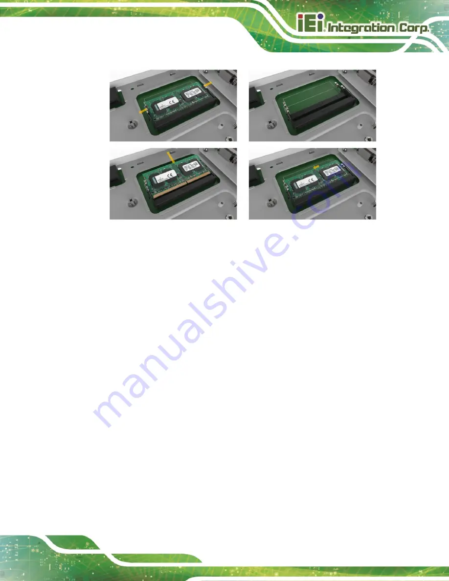
Figure 3-6: Memory Installation 

3.5


Storage Installation 

The TANK-XM811 supports two types of storage, one M.2 M Key & one 2.5" SSD 

3.5.1


M.2 SSD Installation 

Remove the M.2 2280 reserved screws, install the M.2 2280 NVME card, and secure 

the card with the retention screw removed previously (

Figure 3-7

) 

Summary of Contents for TANK-XM811

Page 1: ...r Manual Embedded System with 10th 11th Generation Intel Core Processor Two DDR4 Slot Digital I O HDMI DP Two Gigabit Ethernet RS 232 422 485 RoHS Compliant TANK XM811 Series MODEL Rev 1 00 July 18 20...

Page 2: ...Page II TANK XM811 Revisions Date Version Changes July 18 2022 1 00 Initial release...

Page 3: ...ing out of the use or inability to use the product or documentation even if advised of the possibility of such damages This document contains proprietary information protected by copyright All rights...

Page 4: ...tionary messages should be heeded to help reduce the chance of losing data or damaging the product NOTE These messages inform the reader of essential but non critical information These messages should...

Page 5: ...ON 16 3 1 INSTALLATION PRECAUTIONS 17 3 2 BACK COVER REMOVAL 17 3 3 CPU INSTALLATION 18 3 4 MEMORY INSTALLATION 20 3 5 STORAGE INSTALLATION 21 3 5 1 M 2 SSD Installation 21 3 5 2 2 5 inch SSD Installt...

Page 6: ...L CONNECTORS 42 4 2 1 Clear CMOS Switch J_CMOS1 43 4 2 2 BIOS Programming Connector JSPI1 43 4 2 3 EC Programming Connector EC_SPI1 43 4 2 4 EC Debug Card Connector DEBUG_SPI1 44 4 2 5 System Fan Conn...

Page 7: ...Page VII TANK XM811 B 2 2 Cleaning Tools 56 C ERROR BEEP CODE 57 C 1 PEI BEEP CODES 58 C 2 DXE BEEP CODES 58 D HAZARDOUS MATERIALS DISCLOSURE 59 D 1 ROHS II DIRECTIVE 2015 863 EU 60 D 2 CHINA ROHS 61...

Page 8: ...on 24 Figure 3 10 Back Cover Installation 24 Figure 3 11 Mounting Bracket Retention Screws 25 Figure 3 12 AT ATX Power Mode Switch 26 Figure 3 13 SYS_FAN Connector 27 Figure 3 14 DIO Connector 28 Figu...

Page 9: ...Page IX TANK XM811 Figure 4 2 System Motherboard Rear 41 Figure 4 3 Ethernet Connector 45...

Page 10: ...criptor Security Override Jumper Settings 37 Table 4 1 Peripheral Interface Connectors 42 Table 4 2 Clear CMOS Switch J_CMOS1 43 Table 4 3 BIOS Programming Connector Pinouts JSPI1 43 Table 4 4 EC Prog...

Page 11: ...TANK XM811 Page 1 Chapter 1 1 Introduction...

Page 12: ...e environments It is powered by 12th generation Intel Core processor with Intel Q470 chipset and has two 260 pin DDR4 SDRAM SO DIMM slots supporting up to 64GB memory 8GB preinstalled The TANK XM811 S...

Page 13: ...o 4 6GHz 12 core TDP 35W TANK XM811 i9D R10 Intel Core i9 12900TE 1 1GHz up to 4 8GHz 16 core TDP35W Table 1 1 TANK XM811 Series Model Variations 1 3 Features The TANK XM811 Series features are listed...

Page 14: ...Core i9 12900TE 1 1GHz up to 4 8GHz 16 core TDP 35W Intel Core i7 12700TE 1 4GHz up to 4 6GHz 12 core TDP 35W Intel Core i5 12500TE 1 9GHz up to 4 3GHz 6 core TDP 35W Chipset Intel R680E System Memor...

Page 15: ...ll mount Operating Temperature 20 C 60 C with air flow CPU TDP 35W SSD 20 C 50 C with air flow CPU TDP 65W SSD 10 95 non condensing Storage Temperature 40 C 85 C 10 95 non condensing Operating Shock H...

Page 16: ...Page 6 TANK XM811 1 5 Front Panel The front panel of the TANK XM811 Series has the following features Figure 1 2 Figure 1 2 Front Panel...

Page 17: ...TANK XM811 Page 7 1 6 Rear Panel The rear panel of the TANK XM811 Series is shown below Figure 1 3 Rear Panel...

Page 18: ...Page 8 TANK XM811 1 7 Physical Dimensions The physical dimensions of the TANK XM811 are shown in 507HFigure 1 4 Figure 1 4 Physical Dimensions...

Page 19: ...TANK XM811 Page 9 Chapter 2 2 Unpacking...

Page 20: ...Wearing a simple anti static wristband can help to prevent ESD from damaging the board Self grounding Before handling the board touch any grounded conducting material During the time the board is hand...

Page 21: ...on Contact the IEI reseller or vendor you purchased the TANK XM811 Series from or contact an IEI sales representative directly To contact an IEI sales representative please send an email to sales ieiw...

Page 22: ...y Item and Part Number Image Standard 1 2 pin terminal block 1 4 pin terminal block 1 Chassis screws The following table lists the optional items that can be purchased separately Optional Wi Fi module...

Page 23: ...40 010180 200 RS Power cord P N 32000 000002 RS 8 Port POE LAN card P N GPOE XM81 8P R10 M 2 PCIe mini expansion card P N GPOE XM81 8P R10 2 slot backplane PCIe x16 PCIe x4 P N TXCBP XM81 2A R10 2 slo...

Page 24: ...t backplane two PCIe x8 two PCIe x4 P N TXCBP XM81 4B R10 4 slot backplane PCIe x16 PCIe x4 two PCI P N TXCBP XM81 4C R10 4 slot backplane PCIe x16 two PCIe x4 PCIe x1 P N TXCBP XM81 G1 PW R10 4 slot...

Page 25: ...TXC XM81 4S R10 4 slot chassis full length graphics card support P N TXC XM81 G1 R10 6 slot chassis two full length graphics card support P N TXC XM81 G2 R10 Expansion fan module P N SF TANK XM81 R10...

Page 26: ...Page 16 TANK XM811 Chapter 3 3 Installation...

Page 27: ...ower cord is still connected to an electrical outlet Qualified Personnel The TANK XM811 Series must be installed and operated only by trained and qualified personnel Maintenance upgrades or repairs ma...

Page 28: ...U Installation To replace the CPU you need to remove the motherboard first Follow the steps below to complete the task Step 1 Remove the 11 spring screws on the motherboard and then take out the mothe...

Page 29: ...the heat conductive block of CPU Figure 3 4 Figure 3 4 CPU Thermal Pad Installation Step 4 Align the motherboard together with the motherboard holder with the 4 positioning rods on the 2 sides place i...

Page 30: ...hemselves the installation procedures are described below Step 1 Open the two handles of the memory slot Step 2 Remove the old memory module and insert a new memory module Carefully align the memory m...

Page 31: ...rage Installation The TANK XM811 supports two types of storage one M 2 M Key one 2 5 SSD 3 5 1 M 2 SSD Installation Remove the M 2 2280 reserved screws install the M 2 2280 NVME card and secure the ca...

Page 32: ...811 Figure 3 7 M 2 Installation 3 5 2 2 5 inch SSD Installtion Place the hard drive into the hard drive bracket and secure the HDD bracket with the hard drive using four screws Figure 3 8 Figure 3 8 H...

Page 33: ...i module follow the steps below Step 1 Remove the M 2 A key retention screw Step 2 Insert the Wi Fi module IEI P N EMB WIFI KIT02I3 R10 including one Intel AX210 wireless Bluetooth function module two...

Page 34: ...10 Figure 3 10 Back Cover Installation 3 8 Mounting the System with Mounting Brackets To mount the embedded system onto a wall or some other surface using the two mounting brackets please follow the s...

Page 35: ...rface Step 5 Align the mounting holes in the sides of the mounting brackets with the predrilled holes in the mounting surface Step 6 Insert four retention screws three in each bracket to secure the sy...

Page 36: ...election The TANK XM811 Series supports AT and ATX power modes The setting can be made through the AT ATX power mode switch on the external peripheral interface panel as shown below Figure 3 12 Figure...

Page 37: ...able input and output for external devices The pinouts for the digital I O connector are listed in the table below Table 3 1 Figure 3 14 PIN NO DESCRIPTION PIN NO DESCRIPTION 1 GND 2 DIN0 3 DIN1 4 DIN...

Page 38: ...P devices please plug in HDMI DP connector in the right direction as shown below Figure 3 15 HDMI DP Connection 3 9 5 LAN Connectors The LAN connectors allow connection to an external network Step 1 L...

Page 39: ...tor into the on board RJ 45 connector Figure 3 17 RJ 45 Ethernet Connector The RJ 45 Ethernet connector has two status LEDs one green and one yellow The green LED indicates activity on the port and th...

Page 40: ...r supply into the terminal block Make sure that the power and ground wires are attached to the correct sockets of the connector Figure 3 18 Figure 3 18 4 pin Terminal Block 3 9 7 Power Input 4 pin DIN...

Page 41: ...w Table 3 3 Figure 3 20 PIN NO RS232 RS422 RS485 1 DCD TX TX 2 RXD TX TX 3 TXD RX 4 DTR RX 5 GND 6 DSR 7 RTS 8 CTS 9 RI Table 3 3 RS 232 COM1 COM4 RS 232 422 485 COM5 COM6 Connector Pinouts Figure 3 2...

Page 42: ...ut voltage is being fed into the system Incorrect voltages applied to the system may cause damage to the internal electronic components and may also cause injury to the user Power on the system press...

Page 43: ...tors on the rear panel Power 1 connector is a DIN connector block that supports ACC On signal Power 2 connector is a 4 pin terminal that can directly connect to a power adapter The supported power inp...

Page 44: ...23 Power Connectors Power LED Indicator Description Breathing Orange Standby mode Solid blue Power on mode Table 3 4 Power LED Indicators Description NOTE The power LED turns off when the power cable...

Page 45: ...nd all the relevant software utilities and documentation Figure 3 24 IEI Resource Download Center 3 12 1 Driver Download To download drivers from IEI Resource Download Center follow the steps below St...

Page 46: ...llowing window You can download the entire ISO file or click the small arrow to find an individual driver and click the file name to download NOTE To install software from the downloaded ISO image fil...

Page 47: ...ollowing sections 3 13 1 Flash Descriptor Security Override Jumper The Descriptor Security Override jumper J_FLASH1 allows users to enable or disable the ME firmware update Refer to Figure 3 25 and Ta...

Page 48: ...ity Override jumper Step 2 Update the BIOS and ME firmware and then turn off the system power Step 3 Remove the metal clip on the Flash Descriptor Security Override jumper or return to its default set...

Page 49: ...TANK XM811 Page 39 4 System Motherboard Chapter 4...

Page 50: ...4 1 Overview This chapter details all the jumpers and connectors of the system motherboard 4 1 1 Layout The figures below show all the connectors and jumpers of the system motherboard Figure 4 1 Syste...

Page 51: ...TANK XM811 Page 41 Figure 4 2 System Motherboard Rear...

Page 52: ...programming connector 8 pin header EC_JSP1 EC debug card connector 6 pin box header DBG _JSP1 Flash override jumper 3 pin header ME_FLASH1 I2C BUS connector 4 pin box header I2C1 M 2 slot PCIe x2 int...

Page 53: ...r JSPI1 PIN NO DESCRIPTION PIN NO DESCRIPTION 1 V3 3M_SPI_CON 2 SPI_CS 0_SW 3 SPI_SO_SW 4 SPI_CLK_SW 5 SPI_SI_SW 6 GND Table 4 3 BIOS Programming Connector Pinouts JSPI1 4 2 3 EC Programming Connector...

Page 54: ...ION PIN NO DESCRIPTION 1 VBATT 2 GND Table 4 7 Battery Connector BAT1 4 3 External Interface Panel Connectors The table below shows a list of the external interface panel connectors on the system moth...

Page 55: ...4 pin switch POWER RS 232 connector DB 9 COM1 COM2 COM3 COM4 System fan connector 4 pin box header SYS_FAN Digital I O connector DB 15 DIO Remote power connector 2 pin terminal block Remote Power Tabl...

Page 56: ...5 Gb s Table 4 10 Connector LEDs 4 3 2 Power Input Connector DC Jack PWR1 PIN NO DESCRIPTION PIN NO DESCRIPTION 1 DC_IN1 2 GND 3 DC_IN1 4 GND 5 GND Table 4 11 Power Input Connector PWR1 4 3 3 Power In...

Page 57: ...TANK XM811 Page 47 Appendix A A Regulatory Compliance...

Page 58: ...014 53 EU English IEI Integration Corp declares that this equipment is in compliance with the essential requirements and other relevant provisions of Directive 2014 53 EU Bulgarian IEI Integration Cor...

Page 59: ...o Italian IEI Integration Corp dichiara che questo apparecchio conforme ai requisiti essenziali ed alle altre disposizioni pertinenti stabilite dalla direttiva 2014 53 EU Latviski Latvian IEI Integrat...

Page 60: ...in conformitate cu cerin ele esen iale i cu celelalte prevederi relevante ale Directivei 2014 53 EU Slovensko Slovenian IEI Integration Corp izjavlja da je ta opreme v skladu z bistvenimi zahtevami in...

Page 61: ...ce at his own expense Federal Communication Commission Interference Statement This equipment has been assembled with components that comply with the limits for a Class B digital device pursuant to Par...

Page 62: ...Page 52 TANK XM811 Appendix B B Safety Precautions...

Page 63: ...is turned off and the power cord is disconnected when moving installing or modifying the system Do not apply voltage levels that exceed the specified voltage range Doing so may cause fire and or an e...

Page 64: ...he following anti static precautions are strictly adhered to Wear an anti static wristband Wearing a simple anti static wristband can help to prevent ESD from damaging any electrical component Self gr...

Page 65: ...2012 19 EU WEEE and must not be disposed of as domestic garbage EU wide legislation as implemented in each Member State requires that waste electrical and electronic products carrying the mark left m...

Page 66: ...ically designed for the purpose In such case the product will be explicitly mentioned in the cleaning tips Below is a list of items to use when cleaning the TANK XM811 Series Cloth Although paper towe...

Page 67: ...TANK XM811 Page 57 Appendix C C Error Beep Code...

Page 68: ...nd 4 Recovery failed 4 S3 Resume failed 7 Reset PPI is not available C 2 DXE Beep Codes Number of Beeps Description 1 Invalid password 4 Some of the Architectural Protocols are not available 5 No Cons...

Page 69: ...TANK XM811 Page 59 Appendix D D Hazardous Materials Disclosure...

Page 70: ...brominated Diphenyl Ethers PBDE Bis 2 ethylhexyl phthalate DEHP Butyl benzyl phthalate BBP Dibutyl phthalate DBP Diisobutyl phthalate DIBP Housing O O O O O O O O O O Printed Circuit Board O O O O O O...

Page 71: ...11 Page 61 D 2 China RoHS RoHS RoHS Pb Hg Cd CR VI PBB PBDE O O O O O O O O O O O O O O O O O O O O O O O O O O O O O O O O O O O O O O O O O O O SJ T11364 2014 GB T26572 2011 X SJ T11364 2014 GB T265...

Reviews: