PPC-F12B/15B/17B/19B-BTi Panel PC
Page 33
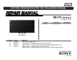
3.11 AT/ATX Mode Selection
AT and ATX power modes can both be used on the PPC-F12B/15B/17B/19B-BTi panel
PC. The selection is made through an AT/ATX switch on the I/O interface panel. The
system is set to AT mode by default. The switch is shown below.
Figure 3-21: AT/ATX Mode Selection
AT/ATX Switch
AT
ATX (Default)
Power
Switch
Position
Off
(O)
The system remains off.
The system remains off.
On
(I)
The system turns on once power is
connected.
Depends on the state selected in the
Restore AC Power Loss
BIOS option
(see
Section 5.4.2
Summary of Contents for PPC-F12B-BT
Page 16: ......
Page 17: ...PPC F12B 15B 17B 19B BTi Panel PC Page 1 1 Introduction Chapter 1 ...
Page 29: ...PPC F12B 15B 17B 19B BTi Panel PC Page 13 2 Unpacking Chapter 2 ...
Page 33: ...PPC F12B 15B 17B 19B BTi Panel PC Page 17 3 Installation Chapter 3 ...
Page 77: ...PPC F12B 15B 17B 19B BTi Panel PC Page 61 Chapter 4 4 System Maintenance ...
Page 79: ...PPC F12B 15B 17B 19B BTi Panel PC Page 63 5 BIOS Setup Chapter 5 ...
Page 114: ...PPC F12B 15B 17B 19B BTi Panel PC Page 98 6 Interface Connectors Chapter 6 ...
Page 134: ...PPC F12B 15B 17B 19B BTi Panel PC Page 118 Appendix A A Regulatory Compliance ...
Page 139: ...PPC F12B 15B 17B 19B BTi Panel PC Page 123 B BIOS Configuration Options Appendix B ...
Page 142: ...PPC F12B 15B 17B 19B BTi Panel PC Page 126 C Safety Precautions Appendix C ...
Page 148: ...PPC F12B 15B 17B 19B BTi Panel PC Page 132 D Watchdog Timer Appendix D ...
Page 151: ...PPC F12B 15B 17B 19B BTi Panel PC Page 135 Appendix E E Hazardous Materials Disclosure ...