NANO-AL EPIC SBC
Page 49
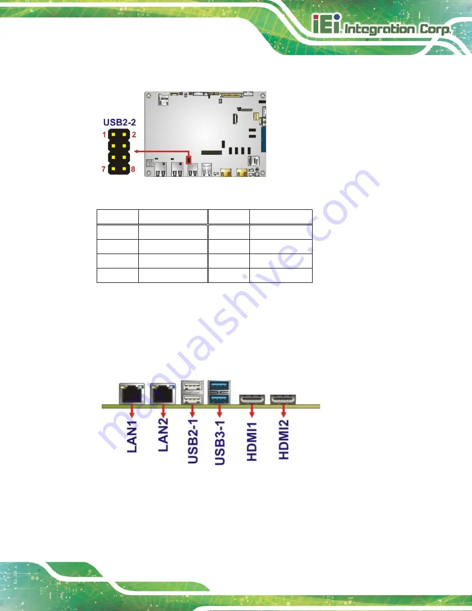
The USB header can connect to two USB 2.0 devices.
Figure 3-33: USB 2.0 Connector Location
Pin
Description
Pin
Description
1
VCC
2
GND
3
DATA-
4
DATA+
5
DATA+
6
DATA-
7
GND
8
VCC
Table 3-30: USB 2.0 Connector Pinouts
3.3 External Interface Connectors
The figure below shows the external peripheral interface connector (EPIC) panel. The
EPIC panel consists of the following:
Figure 3-34: External Interface Connectors
Summary of Contents for NANO-AL
Page 14: ......
Page 15: ...NANO AL EPIC SBC Page 1 Chapter 1 1 Introduction ...
Page 19: ...NANO AL EPIC SBC Page 5 Figure 1 3 Connectors Solder Side ...
Page 25: ...NANO AL EPIC SBC Page 11 Chapter 2 2 Packing List ...
Page 29: ...NANO AL EPIC SBC Page 15 Chapter 3 3 Connectors ...
Page 67: ...NANO AL EPIC SBC Page 53 Chapter 4 4 Installation ...
Page 91: ...NANO AL EPIC SBC Page 77 Chapter 5 5 BIOS ...
Page 131: ...NANO AL EPIC SBC Page 117 Appendix A A Regulatory Compliance ...
Page 133: ...NANO AL EPIC SBC Page 119 B Product Disposal Appendix B ...
Page 135: ...NANO AL EPIC SBC Page 121 Appendix C C BIOS Options ...
Page 138: ...NANO AL EPIC SBC Page 124 Appendix D D Terminology ...
Page 142: ...NANO AL EPIC SBC Page 128 Appendix E E Digital I O Interface ...
Page 145: ...NANO AL EPIC SBC Page 131 Appendix F F Hazardous Materials Disclosure ...


