KINO-SE-i2
P a g e 26
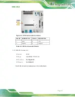
Figure 3-10: Front Panel Connector Location
PIN NO. DESCRIPTION
PIN NO. DESCRIPTION
1
NC
2
3
GND
4
HDD LED+
5
HDD LED-
6
PWR LED+
7
PWR LED+
8
PWR LED-
9
RST BTN+
10
GND
Table 3-10: Front Panel Connector Pinouts
3.2.10
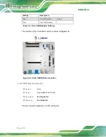
IP MI S lo t
CN La b e l:
IP MI1
CN Typ e :
IPMI slot
CN Lo c a tio n :
See
CN P in o u ts :
See
The IPMI slot is for IPMI module card.
Summary of Contents for KINO-SE-i2
Page 2: ...KINO SE i2 Page II Revis ion Date Version Changes 27 January 2015 1 00 Initial release...
Page 13: ...KINO SE i2 Page 1 1 Introduction Chapter 1...
Page 22: ...KINO SE i2 Page 10 2 Unpacking Chapter 2...
Page 26: ...KINO SE i2 Page 14 3 Connectors Chapter 3...
Page 65: ...KINO SE i2 Page 53 4 Ins tallation Chapter 4...
Page 78: ...KINO SE i2 Page 66 5 BIOS Chapter 5...
Page 111: ...KINO SE i2 Page 99 Appendix A A BIOS Menu Options...
Page 114: ...KINO SE i2 Page 102 Appendix B B Terminology...
Page 119: ...KINO SE i2 Page 107 Appendix C C Watchdog Timer...
Page 122: ...KINO SE i2 Page 110 Appendix D D Hazardous Materials Dis clos ure...

