


IOVU-xxF-AD RISC-based Panel PC
Page 29
3.5.3 10/100/1000 Mbps PoE Connector
NOTE:
For the IOVU-17F-AD model, when a LAN cable is connected to the
10/100/1000 Mbps PoE port, the two USB 2.0 ports will be disabled
due to power consumption limitation.
There is one external RJ-45 LAN connector. The RJ-45 connector enables connection to
an external network.
The RJ-45 connector pinouts are shown below.
Pin
Description
1
LA
2
LAN1_MDX0-
3
LA
4
LA
5
LAN1_MDX2-
6
LAN1_MDX1-
7
LA
8
LAN1_MDX3-
Table 3-3: RJ-45 Connector Pinouts
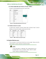
The RJ-45 connector has two status LEDs, one green and one yellow. The green LED
indicates activity on the port and the yellow LED indicates the port is linked (
).
Figure 3-17: RJ-45 Connector
Summary of Contents for IOVU-xxF-AD
Page 11: ...IOVU xxF AD RISC based Panel PC Page 1 Chapter 1 1 Introduction ...
Page 21: ...IOVU xxF AD RISC based Panel PC Page 11 Chapter 2 2 Unpacking ...
Page 26: ...IOVU xxF AD RISC based Panel PC Page 16 Chapter 3 3 Installation ...
Page 42: ...IOVU xxF AD RISC based Panel PC Page 32 Chapter 4 4 Using the IOVU xxF AD ...
Page 67: ...IOVU xxF AD RISC based Panel PC Page 57 Chapter 5 5 Interface Connectors ...
Page 76: ...IOVU xxF AD RISC based Panel PC Page 66 Appendix A A Regulatory Compliance ...
Page 81: ...IOVU xxF AD RISC based Panel PC Page 71 Appendix B B Safety Precautions ...
Page 86: ...IOVU xxF AD RISC based Panel PC Page 76 Appendix C C Hazardous Materials Disclosure ...