IOVU-xxF-AD RISC-based Panel PC
Page 20
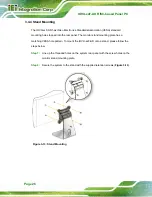
Figure 3-3: Wall-mounting Bracket
Step 6:
Insert the four monitor mounting screws provided in the wall mounting kit into the
four screw holes on the real panel of the IOVU-xxF-AD and tighten until the
screw shank is secured against the rear panel (
).
Step 7:
Align the mounting screws on the monitor rear panel with the mounting holes on
the bracket.
Step 8:
Carefully insert the screws through the holes and gently pull the monitor
downwards until the monitor rests securely in the slotted holes (
Ensure that all four of the mounting screws fit snuggly into their respective
slotted holes.
NOTE:
In the diagram below the bracket is already installed on the wall.
Summary of Contents for IOVU-xxF-AD
Page 11: ...IOVU xxF AD RISC based Panel PC Page 1 Chapter 1 1 Introduction ...
Page 21: ...IOVU xxF AD RISC based Panel PC Page 11 Chapter 2 2 Unpacking ...
Page 26: ...IOVU xxF AD RISC based Panel PC Page 16 Chapter 3 3 Installation ...
Page 42: ...IOVU xxF AD RISC based Panel PC Page 32 Chapter 4 4 Using the IOVU xxF AD ...
Page 67: ...IOVU xxF AD RISC based Panel PC Page 57 Chapter 5 5 Interface Connectors ...
Page 76: ...IOVU xxF AD RISC based Panel PC Page 66 Appendix A A Regulatory Compliance ...
Page 81: ...IOVU xxF AD RISC based Panel PC Page 71 Appendix B B Safety Precautions ...
Page 86: ...IOVU xxF AD RISC based Panel PC Page 76 Appendix C C Hazardous Materials Disclosure ...


