background image


IMBA-XQ354 Motherboard

Page 10 

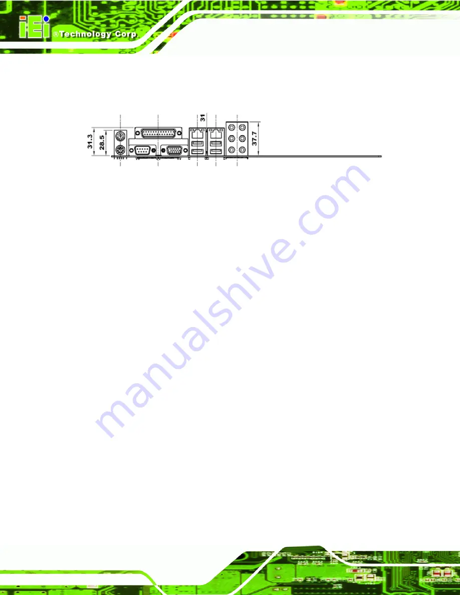
2.2.2 External Interface Panel Dimensions 

External peripheral interface connector panel dimensions are shown in 

8

Figure 2-2


Figure 2-2: External Interface Panel Dimensions (mm) 

Summary of Contents for IMBA-XQ354

Page 1: ...Q354 Motherboard Page i MODEL IMBA XQ354 ATX Motherboard for Intel Core 2 Duo Quad GbE Intel AMT 3 0 PCIe x16 VGA SATA with RAID 0 1 5 10 PCI PCIe x4 HD Audio RoHS Compliant Rev 1 10 April 2011 User M...

Page 2: ...IMBA XQ354 Motherboard Page ii Revision Date Version Changes April 2011 1 10 Initial release...

Page 3: ...s arising out of the use or inability to use the product or documentation even if advised of the possibility of such damages This document contains proprietary information protected by copyright All r...

Page 4: ...Failure to adhere to warning messages may result in permanent damage to the IMBA XQ354 or personal injury to the user Please take warning messages seriously CAUTION Cautionary messages should also be...

Page 5: ...ontained therein can help avoid making mistakes Notes are easy to recognize The word note is written as NOTE both capitalized and bold and is followed by text The text is the cautionary message A note...

Page 6: ...sentative directly To contact an IEI sales representative please send an email to 0sales iei com tw The items listed below should all be included in the IMBA XQ354 package 1 x IMBA XQ354 single board...

Page 7: ...IBLE PROCESSORS 11 2 5 INTEL Q35 NORTHBRIDGE CHIPSET 12 2 5 1 Front Side Bus 13 2 5 2 Memory Controller 14 2 5 3 PCIe x16 Interface 14 2 5 4 Graphics and Display Features 14 2 5 4 1 VGA Display Capabi...

Page 8: ...lel Port 24 2 7 2 Fintek F81216DG Serial Port Chip 24 2 8 ENVIRONMENTAL AND POWER SPECIFICATIONS 24 2 8 1 System Monitoring 24 2 8 2 Power Consumption 25 3 PACKING LIST 26 3 1 ANTI STATIC PRECAUTIONS...

Page 9: ...55 4 2 18 Trusted Platform Module TPM Connector 56 4 2 19 USB Connectors 57 4 3 EXTERNAL INTERFACE CONNECTORS 58 4 3 1 Audio Connector 59 4 3 2 Ethernet Connector 60 4 3 3 Keyboard and Mouse Connector...

Page 10: ...racket 87 5 5 7 USB Cable Four Port 88 5 6 EXTERNAL PERIPHERAL INTERFACE CONNECTION 90 5 6 1 Keyboard and Mouse 90 5 6 2 LAN 91 5 6 3 Parallel Device Connection 92 5 6 4 Serial Device 93 5 6 5 USB 94...

Page 11: ...2 Boot Device Priority 138 6 5 3 Hard Disk Drives 139 6 5 4 CD DVD Drives 140 6 5 5 Removable Drives 141 6 6 SECURITY 142 6 7 CHIPSETS 143 6 7 1 Northbridge Chipset Configuration 144 6 7 2 Southbridg...

Page 12: ...198 E ADDRESS MAPPING 201 E 1 DIRECT MEMORY ACCESS DMA 202 E 2 INPUT OUTPUT IO 203 E 3 INTERRUPT REQUEST IRQ 205 E 4 MEMORY 206 F COMPATIBILITY 207 F 1 COMPATIBLE OPERATING SYSTEMS 208 F 2 COMPATIBLE...

Page 13: ...IMBA XQ354 Motherboard Page xiii H 2 2 Sound Effect Manager Configuration Options 218...

Page 14: ...4 6 Digital I O Connector Locations 39 Figure 4 7 CPU Fan Connector Location 40 Figure 4 8 System Fan Connector Location 41 Figure 4 9 34 pin FDD Connector Location 42 Figure 4 10 Front Panel Connecto...

Page 15: ...ge Setting Select Jumper Location 81 Figure 5 11 SPDIF Out Selection Jumper Pinout Location 82 Figure 5 12 Dual RS 232 Cable Installation 84 Figure 5 13 Single RS 232 Cable Installation 85 Figure 5 14...

Page 16: ...InstallShield Wizard Welcome Screen 163 Figure 7 23 Installation Wizard Finished 164 Figure 7 24 SATA RAID Driver Installation Program 165 Figure 7 25 SATA RAID Setup Program Icon 166 Figure 7 26 Ins...

Page 17: ...e 8 3 Change Intel ME Password 180 Figure 8 4 Verify New Password 180 Figure 8 5 Intel AMT Configuration 180 Figure 8 6 Provision Model 181 Figure 8 7 Intel AMT 3 0 Mode 181 Figure 8 8 Enterprise 182...

Page 18: ...uts 41 Table 4 9 System Fan Connector Pinouts 42 Table 4 10 34 pin FDD Connector Pinouts 43 Table 4 11 Front Panel Connector Pinouts 44 Table 4 12 Infrared Connector Pinouts 45 Table 4 13 PCIe x4 Pino...

Page 19: ...le 4 29 VGA Connector Pinouts 65 Table 5 1 Jumpers 77 Table 5 2 Clear CMOS Jumper Settings 78 Table 5 3 COM Port Pin 9 Function Select Jumper Settings 80 Table 5 4 COM Port Pin 9 Voltage Setting Selec...

Page 20: ...ation 122 BIOS Menu 12 AHCI Configuration 123 BIOS Menu 13 Intel AMT Configuration 124 BIOS Menu 14 ME Subsystem Configuration 125 BIOS Menu 15 Remote Access Configuration Advanced 127 BIOS Menu 16 Tr...

Page 21: ...IMBA XQ354 Motherboard Page 1 Chapter 1 1 Introduction...

Page 22: ...RAID 0 support allows for increased data throughput for applications requiring quick data access RAID 1 5 and 10 provide data redundancy allowing for the failure of one or more disks without losing d...

Page 23: ...m crashes Powerful processor options are ideal for computing intensive applications Data is protected through fast and reliable SATA RAID storage 1 1 2 Features Some of the IMBA XQ354 motherboard feat...

Page 24: ...1 2 1 Connectors The IMBA XQ354 has the following connectors onboard 1 x ATX power connector CPU 1 x ATX power connector system 1 x Audio connector 1 x CD in connector 1 x Digital I O DIO connector 2...

Page 25: ...6 x Audio jack connectors 2 x Ethernet connectors 1 x Keyboard connector 1 x Mouse connector 1 x Parallel port connector 1 x Serial port connectors 4 x USB ports 1 x VGA connector The IMBA XQ354 has t...

Page 26: ...6 MHz or 1333 MHz Northbridge Chipset Intel Q35 Southbridge Chipset Intel ICH9DO Memory Supports four dual channel 2 0 GB max 667 MHz or 800 MHz DDR2 SDRAM DIMMs system max 8 0 GB Expansion Slots 1 x...

Page 27: ...og Timer Software Programmable supports 1 255 sec system reset Trusted Platform Module Supports TPM v1 2 and above Power Supply ATX supported Fans 1 x 4 pin CPU cooling fan 2 x 3 pin system cooling fa...

Page 28: ...IMBA XQ354 Motherboard Page 8 Chapter 2 2 Detailed Specifications...

Page 29: ...ew This chapter describes the specifications and on board features of the IMBA XQ354 in detail 2 2 Dimensions 2 2 1 Board Dimensions The dimensions of the board are listed below Length 305 mm Width 24...

Page 30: ...BA XQ354 Motherboard Page 10 2 2 2 External Interface Panel Dimensions External peripheral interface connector panel dimensions are shown in 8Figure 2 2 Figure 2 2 External Interface Panel Dimensions...

Page 31: ...ow 8Figure 2 3 shows the data flow between the system chipset the CPU and other components installed on the motherboard Figure 2 3 Data Flow Block Diagram 2 4 Compatible Processors The IMBA XQ354suppo...

Page 32: ...Controller Hub GMCH that supports a range of Intel processors as listed in the previous section The Intel Q35Intel Q35 Northbridge supports an 800 1066 1333 MHz FSB The IMBA XQ354 supports up to 2 0...

Page 33: ...Northbridge Connections 2 5 1 Front Side Bus The Intel Q35Intel Q35 Northbridge supports processors with the following FSB speeds 800 MHz 1066 MHz 1333 MHz The LGA775 socket Intel Q35Intel Q35 Northbr...

Page 34: ...per DIMM Memory bandwidth o 6 4 GB s in single channel or dual channel asymmetric mode o 12 8 GB s in dual channel interleaved mode assuming DDR2 800 MHz 2 5 3 PCIe x16 Interface The Intel Q35Intel Q3...

Page 35: ...ronous transfer capabilities Some of the features of the DMI include 2 0 GB s point to point DMI to ICH9DO 1 0 GB s in each direction 100 MHz reference clock shared with PCI Express Graphics Attach 32...

Page 36: ...e IMBA XQ354 has the features listed below Complies with PCI Express Base Specification Revision 11 Complies with PCI Local Bus Specification Revision 2 3 and supports 33 MHz PCI operations Supports A...

Page 37: ...acks on the rear panel and audio headers on the board 2 6 2 Gigabit Ethernet Controllers The Intel ICH9DO Southbridge integrated Gigabit Ethernet MAC is connected to the Intel 82566DM PHY chip and the...

Page 38: ...ome of the features of the Intel 82566DM are listed below 10 Mb s 100 Mb s or 1000 Mb s Supports Intel Active Management TechnologyS Supports Intel Virtualization Technology through the Intel Virtual...

Page 39: ...2 6 4 PCI Interface The PCI interface on the ICH9DO is compliant with the PCI Revision 2 3 implementation Some of the features of the PCI interface are listed below PCI Revision 2 3 compliant 33 MHz...

Page 40: ...mode 3 0 Gb s data transfer speeds are supported 2 6 8 Serial Peripheral Interface SPI BIOS The 4 pin SPI is connected to an SPI BIOS chip A licensed copy of AMI BIOS is preinstalled on the SPI BIOS...

Page 41: ...he LPC bus The iTE IT8718F Super I O chipset and connected components are shown in 8Figure 2 6 below Figure 2 6 iTE IT8718F Super I O The iTE IT8718F is an LPC interface based Super I O device that co...

Page 42: ...e Intel Low Pin Count Specification Rev 1 0 The LPC interface supports both LDRQ and SERIRQ protocols as well as PCI PME interfaces 2 7 1 2 16C550 UARTs The onboard Super I O has two integrated 16C550...

Page 43: ...he fan speed controller on the Super I O The fan speed is then reported in the BIOS 2 7 1 6 Floppy Disk Controller The Super I O floppy disk controller has the following specifications Supports floppy...

Page 44: ...he serial port chipset is interfaced to the Southbridge chipset through the LPC bus Some of the features are listed below Supports LPC interface Totally provides 4 UART 16550 asynchronous ports o 3 x...

Page 45: ...5 V 1 25 V VBAT 2 8 2 Power Consumption 8Table 2 1 shows the power consumption parameters for the IMBA XQ354 with a 2 66 GHz E6850 Intel Core 2 Duo CPU 1333 MHz FSB and 8 0 GB of 800 MHz DDR2 RAM run...

Page 46: ...IMBA XQ354 Motherboard Page 26 Chapter 3 3 Packing List...

Page 47: ...stband can help to prevent ESD from damaging the board Self grounding Before handling the board touch any grounded conducting material During the time the board is handled frequently touch any conduct...

Page 48: ...rom or contact an IEI sales representative directly by sending an email to 33sales iei com tw 3 3 1 Package Contents The IMBA XQ354 is shipped with the following components Quantity Item and Part Numb...

Page 49: ...nstallation Guide Table 3 1 Packing List 3 3 2 Optional Items The IMBA XQ354 is shipped with the following components Item and Part Number Image Dual USB cable w bracket P N CB USB02 RS 4 port USB cab...

Page 50: ...1 20 pin Infineon TPM software management tool firmware V3 17 P N TPM IN01 R11 PCIe x16 VGA output SDVO card supports dual display IEI CPU board only P N SDVO 100VGA R10 PCIe x16 DVI output SDVO card...

Page 51: ...IMBA XQ354 Motherboard Page 31 Chapter 4 4 Connector Pinouts...

Page 52: ...eral interface connector locations Section 8584 1 2 lists all the peripheral interface connectors seen in Section 8684 1 2 4 1 1 IMBA XQ354 Layout 8Figure 4 1 shows the on board peripheral connectors...

Page 53: ...der FPAUDIO1 CD in connector 4 pin header CDIN1 Digital I O connector 10 pin header DIO1 Fan connector CPU 4 pin wafer CPU_FAN1 Fan connector System 3 pin wafer SYS_FAN1 SYS_FAN2 Floppy disk connector...

Page 54: ...ctors 4 1 3 External Interface Panel Connectors 8Table 4 2 lists the rear panel connectors on the IMBA XQ354 Detailed descriptions of these connectors can be found in Section 8684 1 Connector Type Lab...

Page 55: ...s complete descriptions of all the internal peripheral connectors on the IMBA XQ354 4 2 1 ATX CPU Power Connector CN Label CPU12 V1 CN Type 4 pin ATX power connector 1x4 CN Location See 8Figure 4 2 CN...

Page 56: ...e ATX connector is connected to an external ATX power supply Power is provided to the system from the power supply through this connector Figure 4 3 ATX Power Connector Pinout Locations PIN NO DESCRIP...

Page 57: ...onnector Pinouts 4 2 3 Audio Connector CN Label FPAUDIO1 CN Type 10 pin header CN Location See 8Figure 4 4 CN Pinouts See 8Table 4 5 The 10 pin audio connector is connected to external audio devices i...

Page 58: ...C 9 Line left 10 GND Table 4 5 Audio Connector Pinouts 4 2 4 CD In Connector CN Label CD_IN1 CN Type 4 pin header CN Location See 8Figure 4 5 CN Pinouts See 8Table 4 6 The 4 pin audio CD in connector...

Page 59: ...bel DIO1 CN Type 10 pin header 2x5 CN Location See 8Figure 4 6 CN Pinouts See 8Table 4 7 The digital input output connector is managed through a Super I O chip The Digital I O connector pins are user...

Page 60: ...8Figure 4 7 CN Pinouts See 8Table 4 8 The cooling fan connector provides a 12 V 500mA current to a CPU cooling fan The connector has a rotation pin to get rotation signals from fans and notify the sys...

Page 61: ...gure 4 8 CN Pinouts See 8Table 4 9 The cooling fan connector provides a 12 V 500mA current to a system cooling fan The connector has a rotation pin to get rotation signals from fans and notify the sys...

Page 62: ...Floppy Disk Connector CN Label FDD1 CN Type 34 pin header 2x17 CN Location See 8Figure 4 9 CN Pinouts See 8Table 4 10 The floppy disk connector is connected to a floppy disk drive The IMBA XQ354 suppo...

Page 63: ...23 GND 24 WRITE GATE 25 GND 26 TRACK 0 27 GND 28 WRITE PROTECT 29 GND 30 READ DATA 31 GND 32 SIDE 1 SELECT 33 GND 34 DISK CHANGE Table 4 10 34 pin FDD Connector Pinouts 4 2 9 Front Panel Connector CN...

Page 64: ...N Power LED 1 LED 5 V Speaker 2 5 V 3 N C 4 N C 5 Ground 6 N C Power Button 7 Power Button 8 Speaker 9 Power Button Reset 10 N C HDD LED 11 5 V 12 RESET 13 HDLED 14 GND Table 4 11 Front Panel Connecto...

Page 65: ...Figure 4 11 Infrared Connector Pinout Locations PIN NO DESCRIPTION 1 VCC 2 NC 3 IR RX 4 GND 5 IR TX Table 4 12 Infrared Connector Pinouts 4 2 11 PCI Express x4 Slot CN Label PCIE4X_1 PCIE4X_2 and PCIE...

Page 66: ...MDAT A7 N C A8 N C B7 GND B8 3 3 V A9 3 3 V A10 3 3 V B9 N C B10 3 3 V A11 RESET A12 GND B11 WAKE B12 N C A13 REFCLK A14 REFCLK B13 GND B14 HSOp 0 A15 GND A16 HSIp 0 B15 HSOn 0 B16 GND A17 HSIn 0 A18...

Page 67: ...N Location See 8Figure 4 13 CN Pinouts See 8Table 4 14 Side A 8Table 4 15 Side B PCIe x16 expansion devices can be inserted into the PCIe x16 slot Figure 4 13 PCIe x16 Connector Location PIN NAME PIN...

Page 68: ...p 0 A38 GND A59 GND A80 HSIp 15 A18 HSIn 0 A39 HSIp 5 A60 HSIp 10 A81 HSIn 15 A19 GND A40 HSIn 5 A61 HSIn 10 A82 GND A20 RSVD A41 GND A62 GND A21 GND A42 GND A63 GND Table 4 14 PCIe x16 Side A Pinouts...

Page 69: ...HSOn 15 B17 PRSNT 2 B38 HSOn 5 B59 HSOn 10 B80 GND B18 GND B39 GND B60 GND B81 PRSNT 2 B19 HSOp 1 B40 GND B61 GND B82 RSVD 2 B20 HSOn 1 B41 HSOp 6 B62 HSOp 11 B21 GND B42 HSOn 6 B63 HSOn 11 Table 4 15...

Page 70: ...PTION PIN NO DESCRIPTION A1 TRST B1 12 V A2 12 V B2 TCK A3 TMS B3 GND A4 TDI B4 TDO A5 5 V B5 5 V A6 INTA B6 5 V A7 INTC B7 INTB A8 5 V B8 INTD A9 RESERVED3 B9 PRSNT1 A10 5 V B10 RESERVED1 A11 RESERVE...

Page 71: ...B23 AD27 A24 GND B24 AD25 A25 AD24 B25 3 3 V A26 IDSEL B26 C BE3 A27 3 3 V B27 AD23 A28 AD22 B28 GND A29 AD20 B29 AD21 A30 GND B30 AD19 A31 AD18 B31 3 3 V A32 AD16 B32 AD17 A33 3 3 V B33 C BE2 A34 FRA...

Page 72: ...V B59 5 V A60 REQ64 B60 ACK64 A61 5 V B61 5 V A62 5 V B62 5 V Table 4 16 PCI Slot 4 2 14 SATA Drive Connectors CN Label SATA1 SATA2 SATA3 SATA4 SATA5 and SATA6 CN Type SATA drive connectors CN Locati...

Page 73: ...O DESCRIPTION 1 GND 2 TX 3 TX 4 GND 5 RX 6 RX 7 GND Table 4 17 SATA Drive Connector Pinouts 4 2 15 SPDIF Connector CN Label SPDIF1 CN Type 5 pin header CN Location See 8Figure 4 16 CN Pinouts See 8Tab...

Page 74: ...le 4 18 SPDIF Connector Pinouts 4 2 16 Serial Port Connectors CN Label COM2 COM3 COM4 COM5 COM6 CN Type 9 pin box headers 2x5 CN Location See 8Figure 4 17 CN Pinouts See 8Table 4 19 The 10 pin serial...

Page 75: ...D 3 Transmit Data TXD 4 Data Terminal Ready DTR 5 Ground GND 6 Data Set to Ready DSR 7 Request to Send RTS 8 Clear to Sent CTS 9 Ring Indicator RI 10 N C Table 4 19 Serial Port Connector Pinouts 4 2 1...

Page 76: ...RIPTION 1 VCC 2 GND 3 CS 4 CLOCK 5 SO 6 SI 7 NC 8 NC Table 4 20 SPI Flash Connector 4 2 18 Trusted Platform Module TPM Connector CN Label TPM1 CN Type 40 pin header 2x20 CN Location See 9Figure 4 19 C...

Page 77: ...GND2 3 LFRAME 4 KEY 5 LRESET 6 5 V 7 LAD3 8 LAD2 9 3 V 10 LAD1 11 LAD0 12 GND3 13 SCL 14 SDA 15 SB3 V 16 SERIRQ 17 GND1 18 GLKRUN 19 LPCPD 20 LDRQ Table 4 21 TPM Connector Pinouts 4 2 19 USB Connector...

Page 78: ...ear panel The USB ports are used for I O bus expansion Figure 4 20 USB Connector Pinout Locations PIN NO DESCRIPTION PIN NO DESCRIPTION 1 VCC 2 GND 3 DATA 4 DATA 5 DATA 6 DATA 7 GND 8 VCC Table 4 22 U...

Page 79: ...ected to external audio devices as specified below CEN LFE Out Orange Connects to the center speaker and sub woofer Surround Out Black Connects to a speaker on the left and right Side Out Gray Connect...

Page 80: ...USB01 LAN2_USB23 CN Type RJ 45 CN Location See 9Figure 4 21 CN Pinouts See 9Table 4 23 A 10 100 1000 Mb s connection can be made to a Local Area Network PIN DESCRIPTION PIN DESCRIPTION 1 TX 5 N C 2 N...

Page 81: ...K LED Status Description Status Description GREEN ON 100 MB OFF 10 MB YELLOW ON Linked Flashing Activity Table 4 24 Connector LEDs 4 3 3 Keyboard and Mouse Connector CN Label KB_MS1 CN Type PS 2 CN Lo...

Page 82: ...n See 9Figure 4 21 CN Pinouts See 9Table 4 26 The 26 pin parallel port connector connects to a parallel port connector interface or some other parallel port device such as a printer PIN NO DESCRIPTION...

Page 83: ...Port Connector Location 4 3 5 Serial Port Connector CN Label COM1 CN Type DB 9 connector CN Location See 9Figure 4 21 CN Pinouts See 9Table 4 27 and 9Figure 4 26 The RS 232 serial connector provides s...

Page 84: ...ovides connectivity to five additional USB devices USB devices connect directly to the USB connectors on the rear panel PIN DESCRIPTION PIN DESCRIPTION 1 5 V 5 5 V 2 D3 6 D4 3 D3 7 D4 4 GND 8 GND Tabl...

Page 85: ...e 65 PIN DESCRIPTION PIN DESCRIPTION PIN DESCRIPTION 1 RED 6 GROUND 11 NC 2 GREEN 7 GROUND 12 SDA 3 BLUE 8 GROUND 13 HSYNC 4 NC 9 NC 14 VSYNC 5 GROUND 10 GROUND 15 SCL Table 4 29 VGA Connector Pinouts...

Page 86: ...IMBA XQ354 Motherboard Page 66 Chapter 5 5 Installation...

Page 87: ...electrical component is handled the following anti static precautions are strictly adhered to Wear an anti static wristband Wearing a simple anti static wristband can help to prevent ESD from damagin...

Page 88: ...ge to the IMBA XQ354 IMBA XQ354 components and injury to the user Before and during the installation please DO the following Read the user manual o The user manual provides a complete description of t...

Page 89: ...The following checklist is provided to ensure the IMBA XQ354 is properly installed All the items in the packing list are present A compatible memory module is properly inserted into the slot The jump...

Page 90: ...lso result in injury to the user The CPU CPU cooling kit and DIMM are the most critical components of the IMBA XQ354 If one of these component is not installed the IMBA XQ354 cannot run 5 3 1 Socket L...

Page 91: ...Step 1 Remove the protective cover Remove the black protective cover by prying it off the load plate To remove the protective cover locate the REMOVE sign and use your fingernail to pry the protective...

Page 92: ...ssed air Step 4 Orientate the CPU properly Make sure the IHS Integrated Heat Sink side is facing upward Step 5 Correctly position the CPU Match the Pin 1 mark with the cut edge on the CPU socket Step...

Page 93: ...Connect the CPU 12 V cable to the 12 After the cooling kit is installed connect the CPU cable to the CPU 12 V power connector Step 0 5 3 2 Socket LGA775 CF 520 Cooling Kit Installation WARNING It is s...

Page 94: ...low Step 1 Place the cooling kit onto the socket LGA775 CPU Make sure the CPU cable can be properly routed when the cooling kit is installed Step 2 Properly align the cooling kit Make sure the four sp...

Page 95: ...the fan cable Connect the cooling kit fan cable to the fan connector on the IMBA XQ354 Carefully route the cable and avoid heat generating chips and fan blades Step 0 5 3 3 DIMM Installation WARNING U...

Page 96: ...must be oriented in such a way that the notch in the middle of the DIMM must be aligned with the plastic bridge in the socket See 9Figure 5 7 Step 3 Insert the DIMM Once properly aligned the DIMM can...

Page 97: ...s installed in the system the jumpers must be set in accordance with the desired configuration The jumpers on the IMBA XQ354 are listed in 9Table 5 1 Description Label Type Clear CMOS J_CMOS1 3 pin he...

Page 98: ...lip back to pins 1 and 2 If the CMOS Settings Wrong message is displayed during the boot up process the fault may be corrected by pressing the F1 to enter the CMOS Setup menu Do one of the following E...

Page 99: ...pecified as either 5 V or as 12 V To do this please refer to the following section The COM Port Pin 9 Function Select jumpers configure pin 9 on the COM3 COM4 COM5 and COM6 connectors Pin 9 on COM3 CO...

Page 100: ...5 9 below Figure 5 9 COM Port Pin 9 Function Select Jumper Location 5 4 3 COM Port Pin 9 Voltage Setting Select Jumper Label J_COM_V3 J_COM_V4 J_COM_V5 and J_COM_V6 Jumper Type 5 pin header Jumper Se...

Page 101: ...tions are shown in 9Table 5 4 COM Port Jumper Pin 9 5 V Pin 9 12 V COM3 J_COM_V3 Short 1 2 Short 2 3 COM4 J_COM_V4 Short 1 2 Short 2 3 COM5 J_COM_V5 Short 1 2 Short 2 3 COM6 J_COM_V6 Short 1 2 Short 2...

Page 102: ...speakers or compressed AC3 data to an external Dolby Digital Decoder via a coaxial cable The SPDIF Out Selection jumper specifies the connection type Jumper settings are shown in 9Table 5 5 and the ju...

Page 103: ...urface 5 5 2 IMBA XQ354 Installation To install the IMBA XQ354 motherboard into the chassis please refer to the reference material that came with the chassis 5 5 3 Dual RS 232 Cable with Slot Bracket...

Page 104: ...gle RS 232 cable consists of one serial port connectors attached to a serial communications cable that is then attached to a D sub 9 male connector that is mounted onto a bracket To install the single...

Page 105: ...chassisStep 0 5 5 5 SATA Drive Connection The IMBA XQ354 is shipped with two SATA drive cables and one SATA drive power cable To connect the SATA drives to the connectors please follow the steps below...

Page 106: ...nect the connector on the other end of the cable to the connector at the back of the SATA drive See 9Figure 5 15 NOTE The SATA power cable is an optional item that must be purchased separately Step 4...

Page 107: ...o connect the USB cable connector please follow the steps below Step 1 Locate the connectors The locations of the USB connectors are shown in Chapter 3 WARNING If the USB pins are not properly aligned...

Page 108: ...5 16 Figure 5 16 Dual USB Cable Connection Step 4 Attach the bracket to the chassis The USB 2 0 connectors are attached to a bracket To secure the bracket to the chassis please refer to the installat...

Page 109: ...tor with pin 1 on the IMBA XQ354 USB connectors Step 3 Insert the cable connectors Once the cable connectors are properly aligned with the USB connectors on the IMBA XQ354 connect the cable connectors...

Page 110: ...ternal peripheral interface connector making sure the pins are properly aligned 5 6 1 Keyboard and Mouse The IMBA XQ354 has a dual PS 2 connector on the external peripheral interface panel The dual PS...

Page 111: ...e connection to an external network To connect a LAN cable with an RJ 45 connector please follow the instructions below Step 1 Locate the RJ 45 connectors The locations of the USB connectors are shown...

Page 112: ...e IMBA XQ354 has a single female DB 25 connector on the external peripheral interface panel for parallel devices Follow the steps below to connect a parallel device to the IMBA XQ354 Step 1 Locate the...

Page 113: ...al Device The IMBA XQ354 has a single female DB 9 connector on the external peripheral interface panel for a serial device Follow the steps below to connect a serial device to the IMBA XQ354 Step 1 Lo...

Page 114: ...USB Series A receptacle connectors provide easier and quicker access to external USB devices Follow the steps below to connect USB devices to the IMBA XQ354 Step 1 Locate the USB Series A receptacle c...

Page 115: ...ow the instructions below Step 1 Locate the female DB 15 connector The location of the female DB 15 connector is shown in Chapter 3 Step 2 Align the VGA connector Align the male DB 15 connector on the...

Page 116: ...up To install the audio devices follow the steps below Step 1 Identify the audio plugs The plugs on your home theater system or speakers may not match the colors on the rear panel If audio plugs are p...

Page 117: ...es Line Out port Lime Connects to a headphone or a speaker With multi channel configurations this port connect to front speakers Microphone Pink Connects a microphone Figure 5 24 Audio Connector Step...

Page 118: ...IMBA XQ354 Motherboard Page 98 Chapter 6 6 BIOS Setup...

Page 119: ...sage appears on the screen 0 If the message disappears before the DELETE key is pressed restart the computer and try again 6 1 2 Using Setup Use the arrow keys to highlight items press ENTER to select...

Page 120: ...uration Changes If the computer cannot boot after changes to the system configuration is made CMOS defaults Use the jumper described in Chapter 5 6 1 5 BIOS Menu Bar The menu bar on top of the BIOS sc...

Page 121: ...of different system components The fields in System Overview cannot be changed The items shown in the system overview include AMI BIOS Displays auto detected BIOS information o Version Current BIOS ve...

Page 122: ...Advanced Use the Advanced menu to configure the CPU and peripheral devices through the following sub menus WARNING Setting the wrong values in the sections below may cause the system to malfunction Ma...

Page 123: ...IMBA XQ354 Motherboard Page 103 BIOS Menu 2 Advanced...

Page 124: ...igure the CPU BIOS Menu 3 CPU Configuration The CPU Configuration menu 9BIOS Menu 3 lists the following CPU details Manufacturer Lists the name of the CPU manufacturer Frequency Lists the CPU processi...

Page 125: ...enu 4 IDE Configuration SATA n Configuration Enhanced Use the SATA n BIOS option to enable the nth SATA drive port Enhanced DEFAULT The nth SATA drive port is activated Disabled The nth SATA drive por...

Page 126: ...detects the presence of IDE devices BIOS displays the status of the auto detected IDE devices The following IDE devices are detected and are shown in the IDE Configuration menu Primary IDE Master Prim...

Page 127: ...grayed out items in the left frame are IDE disk drive parameters automatically detected from the firmware of the selected IDE disk drive The drive parameters are listed as follows Device Lists the de...

Page 128: ...ed 32Bit Data Transfer Enables 32 bit data transfer Type Auto Use the Type BIOS option select the type of device the AMIBIOS attempts to boot from after the Power On Self Test POST is complete Not Ins...

Page 129: ...Multi Sector Transfer on the specified channel The data to and from the device occurs one sector at a time Auto DEFAULT BIOS auto detects Multi Sector Transfer support on the drive on the specified c...

Page 130: ...rd DMA mode 0 selected with a maximum data transfer rate of 2 1 MB s SWDMA1 Single Word DMA mode 1 selected with a maximum data transfer rate of 4 2 MB s SWDMA2 Single Word DMA mode 2 selected with a...

Page 131: ...M A R T Auto Use the S M A R T option to auto detect disable or enable Self Monitoring Analysis and Reporting Technology SMART on the drive on the specified channel S M A R T predicts impending drive...

Page 132: ...ion menu to configure the floppy disk drive connected to the system BIOS Menu 6 IDE Master and IDE Slave Configuration Floppy A Use the Floppy A B option to configure the floppy disk drive Options are...

Page 133: ...ess 3F8 IRQ4 Use the Serial Port1 Address option to select the Serial Port 1 base address Disabled No base address is assigned to Serial Port 1 3F8 IRQ4 DEFAULT I O port address is 3F8 and the interru...

Page 134: ...errupt address is IRQ3 Serial Port2 Mode Normal Use the Serial Port2 Mode option to select the Serial Port2 operational mode Normal DEFAULT Serial Port 2 mode is normal IrDA Serial Port 2 mode is IrDA...

Page 135: ...between the system and the parallel port device and the transmission rates between the two are much faster than the SPP mode EPP ECP The parallel port operates in the extended capabilities port ECP m...

Page 136: ...the operating temperature fan speeds and system voltages BIOS Menu 8 Hardware Health Configuration FAN Mode Setting Full On Mode Use the FAN Mode Setting option to configure the fan mode options for...

Page 137: ...refore cause the system to be damaged The CPU Temp Limit of OFF option can only be set if the CPU FAN Mode Setting option is set to Automatic Mode Use the CPU Temp Limit of OFF option to select the CP...

Page 138: ...rt PWM option can only be set if the CPU FAN Mode Setting option is set to Automatic Mode Use the Fan 3 Start PWM option to select the PWM mode the fan starts to rotate with after the temperature spec...

Page 139: ...that are monitored are System Temperatures The following system temperatures are monitored o CPU Temperature o System Temperature 1 o System Temperature 2 Fan Speeds The CPU cooling fan speed is monit...

Page 140: ...nu 9BIOS Menu 10 to configure the drive connected to SATA connector n BIOS Menu 10 AHCI Port n Configuration Menu Restore on AC Power Loss Last State Use the Restore on AC Power Loss BIOS option to sp...

Page 141: ...r a button on the keyboard is pressed Disabled DEFAULT Wake event not generated by activity on the keyboard or mouse Enabled Wake event generated by activity on the keyboard or mouse Disabled DEFAULT...

Page 142: ...BIOS Menu 11 Advanced ACPI Configuration Suspend Mode S1 POS Use the Suspend Mode option to specify the sleep state the system enters when it is not being used S1 POS The system enters S1 POS sleep s...

Page 143: ...of devices connected to the onboard SATA drive connectors BIOS Menu 12 AHCI Configuration AHCI Port n Not Detected Use the AHCI Port n BIOS option to check what AHCI Advanced Host Controller Interfac...

Page 144: ...to be managed through the Intel Active Management Technology AMT interface The interface is implemented through LAN1 BIOS Menu 13 Intel AMT Configuration Intel AMT Support Disabled Use the Intel AMT S...

Page 145: ...ubsystem Configuration BootBlock HECI Message Enabled Use the BootBlock HECI Message option to enable or disable boot disk sector that contains the Intel AMT Host Embedded Controller Interface HECI me...

Page 146: ...ion to enable or disable the IDE Redirection IDER protocol This allows redirection of CD floppy and DVD drives through the management engine Disabled The IDER protocol is disabled Enabled DEFAULT The...

Page 147: ...l program to display and configure the BIOS settings BIOS Menu 15 Remote Access Configuration Advanced Remote Access Disabled Use the Remote Access option to enable or disable access to the remote fun...

Page 148: ...e access COM1 DEFAULT System is remotely accessed through COM1 COM2 System is remotely accessed through COM2 NOTE Make sure the selected COM port is enabled through the Super I O configuration menu Ba...

Page 149: ...irected after POST Boot Loader Redirection is active during POST and during Boot Loader Always DEFAULT Redirection is always active Some OSes may not work if set to Always Terminal Type ANSI Use the T...

Page 150: ...nu 9BIOS Menu 16 to configure settings related to the Trusted Computing Group TCG Trusted Platform Module TPM BIOS Menu 16 Trusted Computing TCG TPM Support No Use the TCG TPM Support option to config...

Page 151: ...figure the USB settings BIOS Menu 17 USB Configuration USB Functions Enabled Use the USB Function BIOS option to enable or disable USB function support Disabled USB function support disabled Enabled D...

Page 152: ...isabled if no USB devices are connected USB 2 0 Controller Enabled Use the USB 2 0 Controller BIOS option to enable or disable the USB 2 0 controller Disabled USB 2 0 controller disabled Enabled DEFAU...

Page 153: ...he IRQ address to specify what IRQs can be assigned to a particular peripheral device Available DEFAULT The specified IRQ is available to be used by PCI PnP devices Reserved The specified IRQ is reser...

Page 154: ...served for use by Legacy ISA devices Available DMA Channels are DM Channel 0 DM Channel 1 DM Channel 3 DM Channel 5 DM Channel 6 DM Channel 7 Reserved Memory Size Disabled Use the Reserved Memory Size...

Page 155: ...IMBA XQ354 Motherboard Page 135 6 5 Boot Use the Boot menu 99BIOS Menu 19 to configure system boot options BIOS Menu 19 Boot...

Page 156: ...ngs Configuration Quick Boot Enabled Use the Quick Boot BIOS option to make the computer speed up the boot process Disabled No POST procedures are skipped Enabled DEFAULT Some POST procedures are skip...

Page 157: ...ber Lock automatically To use the 10 keys on the keyboard press the Number Lock key located on the upper left hand corner of the 10 key pad The Number Lock LED on the keyboard lights up when the Numbe...

Page 158: ...sabled DEFAULT Cannot be booted remotely through this port Enabled Can be booted remotely through this port 6 5 2 Boot Device Priority Use the Boot Device Priority menu 99BIOS Menu 21 to specify the b...

Page 159: ...ard Disk Drives menu to specify the boot sequence of the available HDDs When the menu is opened the HDDs connected to the system are listed as shown below 1st Drive 2nd Drive 3rd Drive NOTE Only insta...

Page 160: ...to specify the boot sequence of the available CD DVD drives When the menu is opened the CD drives and DVD drives connected to the system are listed as shown below 1st Drive 2nd Drive 3rd Drive NOTE On...

Page 161: ...to specify the boot sequence of the available FDDs When the menu is opened the FDDs connected to the system are listed as shown below 1st Drive 2nd Drive NOTE Only installed removable drives are shown...

Page 162: ...Not Installed If a supervisor password must be installed select this field and enter the password After the password has been added Install appears next to Change Supervisor Password Change User Pass...

Page 163: ...hipsets Use the Chipset menu to access the Northbridge and Southbridge configuration menus WARNING Setting the wrong values for the Chipset BIOS selections in the Chipset BIOS menu may cause the syste...

Page 164: ...pset Configuration Memory Remap Feature Enabled Use the Memory Remap Feature option to allow the overlapped PCI memory above the total physical memory to be remapped Enabling this option allows full u...

Page 165: ...cards Initiate Graphic Adapter Use the Initiate Graphic Adapter option to select the graphics controller used as the primary boot device Select either an integrated graphics controller IGD or a combin...

Page 166: ...troller Disabled Use the HDA Controller option to enable the Southbridge high definition audio controller If the optional AC KIT 833HD has been connected to the system or any other HDA device this opt...

Page 167: ...is activated and can communicate with a remote management server 6 8 Exit Use the Exit menu 9BIOS Menu 29 to load default BIOS values optimal failsafe values and to save configuration changes BIOS Men...

Page 168: ...on to discard the changes and remain in the BIOS configuration setup program Load Optimal Defaults Use the Load Optimal Defaults option to load the optimal default values for each of the parameters on...

Page 169: ...IMBA XQ354 Motherboard Page 149 Chapter 7 7 Software Drivers...

Page 170: ...system 7 3 Chipset Driver 152 7 4 Graphics Driver 154 7 5 LAN Driver 158 7 6 Audio Driver 162 7 7 Intel Matrix Storage Manager Driver 164 7 8 Intel AMT HECI Driver 170 7 9 Intel AMT SOL Driver 173 Ins...

Page 171: ...IMBA XQ354 Motherboard Page 151 Step 2 The screen in 1Figure 7 1 appears Figure 7 1 Start Up Screen Step 3 Click IMBA XQ354 Step 4 The list of drivers in 1Figure 7 2 appears Step 0 Figure 7 2 Drivers...

Page 172: ...llow the steps below Step 1 Click INF inm the drivers list Step 2 Browse to E 1 INF 8 3 1 1009 and double click infinst_autol in 1Figure 7 3 Figure 7 3 Intel Chipset Driver Directory Step 3 The Welcom...

Page 173: ...The Intel license agreement screen appears 1Figure 7 5 Figure 7 5 Intel Chipset Driver License Agreement Step 6 Click YES to accept the agreement and continue Step 7 The Readme file contents are displ...

Page 174: ...7 Figure 7 7 Intel Chipset Driver Complete Installation Screen Step 10 To exit the installation click FINISH S t e p 0 7 4 Graphics Driver To install the chipset driver please follow the steps below...

Page 175: ...re 7 8 Graphics Driver File Step 3 Double click the driver file Step 4 The version information file appears 1Figure 7 9 Figure 7 9 Graphics Driver Readme File Step 5 Click NEXT to continue Step 6 The...

Page 176: ...ard Page 156 Figure 7 10 Graphics Driver Installation Welcome Screen Step 7 Click NEXT to continue Step 8 The license agreement appears 1Figure 7 11 Figure 7 11 GMA Driver License Agreement Step 9 Cli...

Page 177: ...157 Step 10 The Readme file appears 1Figure 7 12 Figure 7 12 GMA Driver Installing Notice Step 11 Click NEXT to continue Step 12 The driver installation progress is shown 1Figure 7 13 Figure 7 13 GMA...

Page 178: ...st be restarted Select Yes to restart the computer now close any other programs first or No to restart it later Click FINISH to complete the installation S t e p 0 7 5 LAN Driver To install the LAN dr...

Page 179: ...59 Figure 7 15 LAN Driver File Step 3 Double click PRO2KXP icon Step 4 The welcome screen appears 1Figure 7 16 Figure 7 16 LAN Driver Welcome Screen Step 5 Click NEXT to continue Step 6 The license ag...

Page 180: ...e Agreement Step 7 Accept the conditions of the license agreement and click NEXT to continue Step 8 The Setup Options screen appears 1Figure 7 18 Figure 7 18 LAN Driver Setup Options Step 9 Select the...

Page 181: ...are ready to install Click INSTALL to begin the installation process 1Figure 7 19 Figure 7 19 LAN Driver Installation Ready Window Step 11 Click INSTALL to begin the driver installation Step 12 The wi...

Page 182: ...ollow the steps below NOTE This driver only needs to be installed if an external audio kit with a RealTek ALC883 codec is installed 7 6 1 BIOS Setup Step 1 Enter the BIOS setup To do this reboot the s...

Page 183: ...the main menu Step 2 Browse to the audio setup file directory 1Figure 7 21 Figure 7 21 Audio Setup File Step 3 The audio driver InstallShield wizard begins 1Figure 7 22 Figure 7 22 InstallShield Wizar...

Page 184: ...started Select Yes to restart the computer immediately after exiting the wizard or No to restart it later Click FINISH to exit the InstallShield Wizard S t e p 0 7 7 Intel Matrix Storage Manager Drive...

Page 185: ...IMBA XQ354 Motherboard Page 165 Figure 7 24 SATA RAID Driver Installation Program Step 3 Double click the INTEL folder Step 4 Double click the iata62_cd exe program icon in 1Figure 7 25...

Page 186: ...erboard Page 166 Figure 7 25 SATA RAID Setup Program Icon Step 5 1Figure 7 26 shows the InstallShield Wizard preparing to guide the user through the rest of the process Figure 7 26 InstallShield Wizar...

Page 187: ...27 shows the Matrix Storage Manager software configuring the installation process Figure 7 27 Matrix Storage Manager Setup Screen Step 7 1Figure 7 28 shows the Matrix Storage Manager welcome screen F...

Page 188: ...s 1Figure 7 29 Read the warning carefully and decide whether or not to continue the installation process Figure 7 29 Matrix Storage Manager Warning Screen Step 9 Click NEXT and a license agreement app...

Page 189: ...ed in the license agreement shown click YES and the Readme information file shown in 1Figure 7 31 appears Figure 7 31 Matrix Storage Manager Readme File Step 11 Read the Readme file information and cl...

Page 190: ...el AMT HECI Driver The Intel AMT HECI drivers are a software interface between the operating system and the AMT subsystem All communications between the OS and AMT is accomplished through the HECI int...

Page 191: ...33 AMT HECI Driver Directory Step 3 Double click the setup file 1Figure 7 34 Step 4 The welcome screen appears 1Figure 7 34 Figure 7 34 AMT HECI Welcome Screen Step 5 Click NEXT to continue Step 6 Th...

Page 192: ...re 7 35 AMT HECI License Agreement Step 7 Click YES to agree to the terms of the agreement and continue installation Step 8 The IAMT Readme file appears 1Figure 7 36 Figure 7 36 AMT HECI Driver Readme...

Page 193: ...er The Intel AMT Serial Over LAN SOL drivers allow remote management of the system through a serial port device redirected through the LAN interface For more information on Intel AMT please visit 3htt...

Page 194: ...otherboard Page 174 Figure 7 38 IAMT Driver Directory Step 3 The welcome screen appears 1Figure 7 39 Figure 7 39 IAMT Welcome Screen Step 4 Click NEXT to continue Step 5 The License Agreement appears...

Page 195: ...5 Figure 7 40 IAMT License Agreement Step 6 Click YES to agree to the terms of the agreement and continue the installation Step 7 The IAMT Readme file appears 1Figure 7 41 Figure 7 41 IAMT Readme File...

Page 196: ...IMBA XQ354 Motherboard Page 176 Step 9 The final installation screen appears 1Figure 7 42 Figure 7 42 Completed Installation Step 10 Click FINISH to complete the IAMT installation S t e p 0...

Page 197: ...IMBA XQ354 Motherboard Page 177 Chapter 8 8 Intel AMT Setup...

Page 198: ...tion Advanced ME Subsystem Configuration Advanced Configure the Intel Management Engine BIOS extension MEBx see Section 1018 2 below Step 4 Properly install the Intel AMT drives Make sure to install b...

Page 199: ...ault ME password Abab12 the Intel default password is admin NOTE The default Intel ME password is admin When the BIOS is cleared the password will reset to admin Figure 8 2 Intel Current ME Password S...

Page 200: ...Password Step 4 Verify the new password by entering again 1Figure 8 4 Figure 8 4 Verify New Password Step 5 Select Intel AMT Configuration and press Enter 1Figure 8 5 Figure 8 5 Intel AMT Configuratio...

Page 201: ...81 Figure 8 6 Provision Model Step 7 When the screen in 1Figure 8 7 prompts enter N and press Enter Figure 8 7 Intel AMT 3 0 Mode Step 8 A message prompts to confirm to Change to Small Business 1Figur...

Page 202: ...Intel AMT Configuration and press Enter A message prompts for disabling network interface Enter N to enable network interface Figure 8 9 Enable Network Interface Step 10 Enable or disable DHCP DHCP i...

Page 203: ...e DNS server address optional Domain name optional Step 11 Make other necessary settings in the Intel MEBx depending on users need Step 12 To exit the Intel MEBx return to the main menu and select Exi...

Page 204: ...10 get the client system IP address in the MS DOS Enter the client system IP address and the port number in the web browser http ip_address 16992 Example http 192 168 1 7 16992 1Figure 8 11 Or simply...

Page 205: ...l AMT Web Login Dialog Step 6 Enter admin as the user name 1Figure 8 12 Step 7 Enter the password changed in the Intel MEBx configuration The default password is Abab12 Step 8 Press OK and the Intel A...

Page 206: ...board Page 186 Figure 8 13 Intel AMT Web Interface NOTE To enhance the platform manageability of theIMBA XQ354 work with the Independent Software Vendors ISV to implement the Intel AMT management util...

Page 207: ...IMBA XQ354 Motherboard Page 187 Appendix A A BIOS Options...

Page 208: ...A R T Auto 111 32Bit Data Transfer Enabled 111 Floppy A 112 Serial Port1 Address 3F8 IRQ4 113 Serial Port1 Mode Normal 113 Serial Port2 Address 2F8 IRQ3 114 Serial Port2 Mode Normal 114 Parallel Addr...

Page 209: ...acy USB Support Enabled 131 USB 2 0 Controller Enabled 132 USB2 0 Controller Mode HiSpeed 132 IRQ Available 133 DMA Channel Available 134 Reserved Memory Size Disabled 134 Quick Boot Enabled 136 Quiet...

Page 210: ...IMBA XQ354 Motherboard Page 190 Discard Changes and Exit 148 Discard Changes 148 Load Optimal Defaults 148 Load Failsafe Defaults 148...

Page 211: ...IMBA XQ354 Motherboard Page 191 Appendix B B Terminology...

Page 212: ...a binary 0 while a high amplitude signal represents a binary 1 BIOS The Basic Input Output System BIOS is firmware that is first run when the computer is turned on and can be configured by the end use...

Page 213: ...Step Technology EIST allows users to modify the power consumption levels and processor performance through application software The application software changes the bus to core frequency ratio and the...

Page 214: ...ansfers between storage devices and the computer chipsets The SATA bus has transfer speeds up to 1 5 Gb s and the SATA II bus has data transfer speeds of up to 3 0 Gb s S M A R T Self Monitoring Analy...

Page 215: ...IMBA XQ354 Motherboard Page 195 Appendix C C Digital I O Interface...

Page 216: ...ase refer to the datasheet for the Super I O chipset C 2 DIO Connector Pinouts The Digital I O port pins and their pin numbers are listed in the table below Pin Description Super I O Pin No Super I O...

Page 217: ...tes the INT 15H BIOS call C 3 2 Enable the DIO Output Function The BIOS interrupt call INT 15H controls the digital I O An assembly program to enable digital I O output functions is listed below MOV A...

Page 218: ...IMBA XQ354 Motherboard Page 198 Appendix D D Watchdog Timer...

Page 219: ...BIOS function call INT 15H is used to control the Watchdog Timer INT 15H AH 6FH Sub function AL 2 Sets the Watchdog Timer s period BL Time out value Its unit second is dependent on the item Watchdog T...

Page 220: ...system resets EXAMPLE PROGRAM INITIAL TIMER PERIOD COUNTER W_LOOP MOV AX 6F02H setting the time out value MOV BL 30 time out value is 48 seconds INT 15H ADD THE APPLICATION PROGRAM HERE CMP EXIT_AP 1...

Page 221: ...IMBA XQ354 Motherboard Page 201 Appendix E E Address Mapping...

Page 222: ...IMBA XQ354 Motherboard Page 202 E 1 Direct Memory Access DMA Figure E 1 Direct Memory Access DMA...

Page 223: ...IMBA XQ354 Motherboard Page 203 E 2 Input Output IO Figure E 2 Input Output IO 1 of 2...

Page 224: ...IMBA XQ354 Motherboard Page 204 Figure E 3 Input Output IO 2 of 2...

Page 225: ...IMBA XQ354 Motherboard Page 205 E 3 Interrupt Request IRQ Figure E 4 Interrupt Request IRQ...

Page 226: ...IMBA XQ354 Motherboard Page 206 E 4 Memory Figure E 5 Memory...

Page 227: ...IMBA XQ354 Motherboard Page 207 Appendix F F Compatibility...

Page 228: ...ta Ultimate 32bit 64bit Linux Mandriva 2008 Linux Ubuntu 8 04 Linux openSuSE 11 0 Linux Fedora 9 F 2 Compatible Processors The following processors have been successfully tested on the IMBA XQ354 CPU...

Page 229: ...es that comply with the specifications may also work on the IMBA XQ354 but have not been tested The following memory modules have been successfully tested on the IMBA XQ354 Manufacturer Capacity Speed...

Page 230: ...IMBA XQ354 Motherboard Page 210 Manufacturer Capacity Speed Type Transcend 2 0 GB 800 MHz DDR2 Umax 2 0 GB 800 MHz DDR2 Adata 2 0 GB 800 MHz DDR2 Table F 2 Compatible Memory Modules...

Page 231: ...IMBA XQ354 Motherboard Page 211 Appendix G G Hazardous Materials Disclosure...

Page 232: ...presences of small quantities of certain materials in the product and is applicable to China RoHS only A label will be placed on each product to indicate the estimated Environmentally Friendly Use Pe...

Page 233: ...t Board X O O O O X Metal Fasteners X O O O O O Cable Assembly X O O O O X Fan Assembly X O O O O X Power Supply Assemblies X O O O O X Battery O O O O O O O This toxic or hazardous substance is conta...

Page 234: ...IMBA XQ354 Motherboard Page 214 RoHS RoHS Pb Hg Cd CR VI PBB PBDE X O O O O X X O O O O X X O O O O X X O O O O O X O O O O X X O O O O X X O O O O X O O O O O O O SJ T11363 2006 X SJ T11363 2006...

Page 235: ...IMBA XQ354 Motherboard Page 215 Appendix H H AC 97 Audio Codec...

Page 236: ...outputs and outputs are located on the rear panel and through pin headers on the board H 1 2 Driver Installation The driver installation has already been described After rebooting the sound effect con...

Page 237: ...the audio drivers Step 2 Click the Sound Effect Manager icon in the system task bar 1Figure H 2 Figure H 2 Sound Effect Manager Icon Task Bar Step 3 The sound effect manager appears 1Figure H 3 Figure...

Page 238: ...OTE The Karaoke Mode is configured in the Sound Effect menu To access Karaoke configuration settings click on the Sound Effect menu tab Sound Effect Karaoke Mode Equalizer Speaker Configuration Speake...

Page 239: ...speaker settings are configured in this menu Configurable options include o Headphone o Channel mode for stereo speaker output o Channel mode for 4 speaker output o Channel mode for 5 1 speaker outpu...

Page 240: ...IMBA XQ354 Motherboard Page 220 Index...

Page 241: ...59 audio jack 59 96 audio jack 59 audio jack 96 audio jack connector 5 B BIOS 99 100 101 106 129 132 137 143 147 C cables dual port USB 87 dual RS 232 cable 83 four port USB 88 SATA drive 85 SATA dri...

Page 242: ...ace 44 parallel port 62 PCI Express x16 slot 45 47 PCI slot 49 S PDIF 53 serial port COM 2 54 SPI flash connector 55 trusted platform module TPM 56 USB internal 57 cooling 83 airflow 83 cooling fan 40...

Page 243: ...frared interface 45 Amplitude Shift Key Infrared 45 ASKIR 45 Serial Infrared 45 SIR 45 infrared interface connector 45 location and pinouts 45 installation checklist 69 IrDA 114 J jumper 77 clear CMOS...

Page 244: ...ck 20 reset button 43 RJ 45 connection 91 single connector 91 RoHS 3 RS 232 54 83 84 cable connection 83 84 COM 2 location and pinouts 54 connector location and pinouts 54 dual cable 83 serial port de...

Page 245: ...56 location and pinouts 56 U unpacking 27 unpacking checklist 28 unpacking precautions 27 USB 58 87 88 131 132 cable dual port 87 four port 88 cable 87 cable 87 cable 88 cable 88 cable connection 88...

Reviews: