641/20/2012164
P a g e 64
IMBA-G412IS A ATX Mo th e rb o a rd
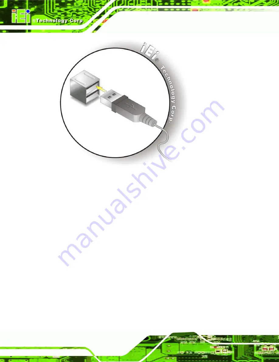
Figure 4-22: USB Connector
4.6.7
VGA Mo n ito r Co n n e c tio n
The IMBA-G412ISA has a single female DB-15 connector on the external peripheral
interface panel. The DB-15 connector is connected to a CRT or VGA monitor. To connect
a monitor to the IMBA-G412ISA, please follow the instructions below.
S te p 1:
Locate the female DB-15 connector
. The location of the female DB-15
connector is shown in
Chapter 3
.
S te p 2:
Align the VGA connector
. Align the male DB-15 connector on the VGA screen
cable with the female DB-15 connector on the external peripheral interface.
S te p 3:
Insert the VGA connector
.
Once the connectors are properly aligned with the
insert the male connector from the VGA screen into the female connector on the
Summary of Contents for IMBA-G412ISA-R20
Page 14: ......
Page 15: ...2012 1 202012 1 20 IMBA G412ISA ATX Motherboard Page 1 Chapter 1 1 Introduction...
Page 24: ...101 20 2012164 Page 10 IMBA G412ISA ATX Motherboard Chapter 2 2 Packing Lis t...
Page 29: ...2012 1 202012 1 20 IMBA G412ISA ATX Motherboard Page 15 Chapter 3 3 Connectors...
Page 55: ...2012 1 202012 1 20 IMBA G412ISA ATX Motherboard Page 41 Chapter 4 4 Ins tallation...
Page 80: ...661 20 2012164 Page 66 IMBA G412ISA ATX Motherboard Chapter 5 5 BIOS...
Page 120: ...1061 20 2012164 Page 106 IMBA G412ISA ATX Motherboard Appendix A A BIOS Options...
Page 124: ...1101 20 2012164 Page 110 IMBA G412ISA ATX Motherboard Appendix B B Terminology...
Page 128: ...1141 20 2012164 Page 114 IMBA G412ISA ATX Motherboard Appendix C C One Key Recovery...
Page 156: ...1421 20 2012164 Page 142 IMBA G412ISA ATX Motherboard Appendix D D Watchdog Timer...
Page 159: ...2012 1 202012 1 20 IMBA G412ISA ATX Motherboard Page 145 Appendix E E Digital I O Interface...


