ICECARE-10W Mobile Sales Assistant
Page 15
Remove any of the stickers on the PCB board. These stickers are required for
warranty validation.
Use the product before verifying all the cables and power connectors are
properly connected.
Allow screws to come in contact with the PCB circuit, connector pins, or its
components.
3.2 Charge the Sytem
To charge the ICECARE-10W Series, follow the steps below.
Step 1:
Connect the ICECARE-10W Series with a power source through the power
adapter came with the package.
Step 2:
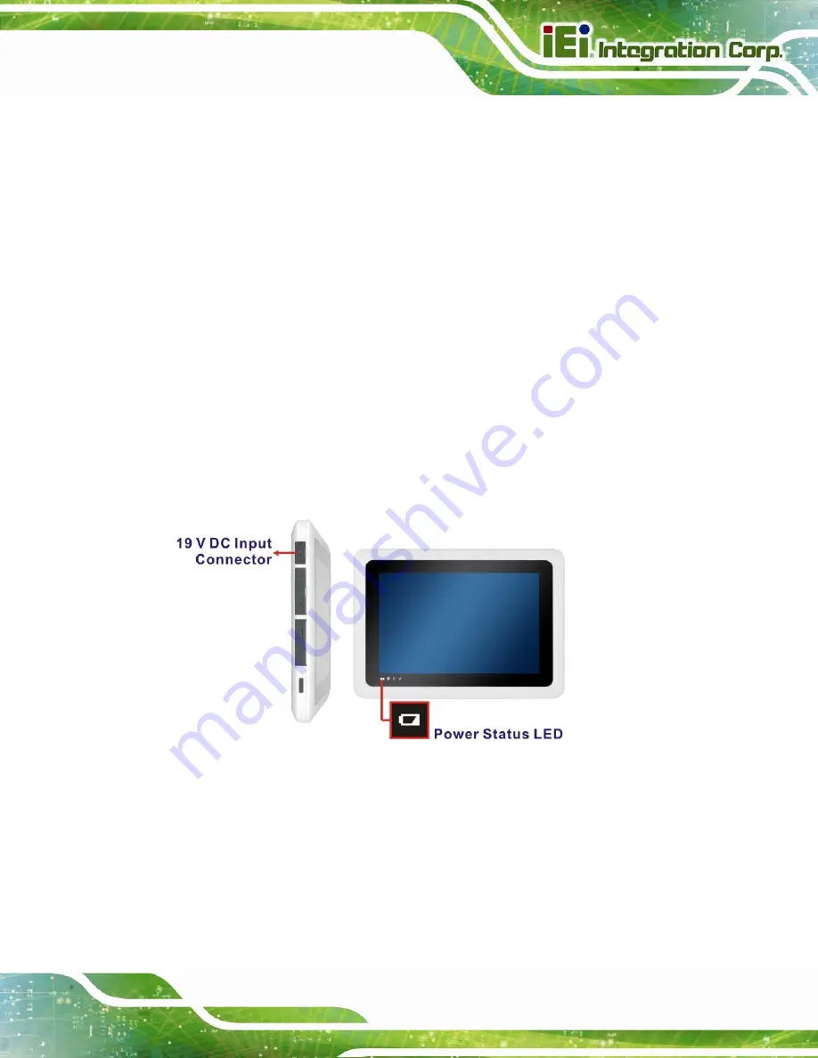
The system starts to charge the battery and the power status LED lights up in
red indicating the battery is being charged. When the battery is fully charged, the
power status LED turns off.
Figure 3-1: Power Input Connector and Power LED Indicator
Step 3:
The user can also turn on the system to check the battery capacity via the
Windows Embedded 7 power management screen (
73
Summary of Contents for IceCare-10W series
Page 12: ......
Page 13: ...ICECARE 10W Mobile Sales Assistant Page 1 Chapter 1 1 Introduction ...
Page 21: ...ICECARE 10W Mobile Sales Assistant Page 9 1 9 Dimensions Figure 1 7 Dimensions units in mm ...
Page 22: ...ICECARE 10W Mobile Sales Assistant Page 10 Chapter 2 2 Unpacking ...
Page 25: ...ICECARE 10W Mobile Sales Assistant Page 13 Chapter 3 3 Hardware Installation ...
Page 47: ...ICECARE 10W Mobile Sales Assistant Page 35 Chapter 4 4 Driver Installation ...
Page 60: ...ICECARE 10W Mobile Sales Assistant Page 48 Chapter 5 5 BIOS Setup ...
Page 88: ...ICECARE 10W Mobile Sales Assistant Page 76 Appendix A A Safety Precautions ...
Page 94: ...ICECARE 10W Mobile Sales Assistant Page 82 Appendix B B BIOS Options ...
Page 97: ...ICECARE 10W Mobile Sales Assistant Page 85 Appendix C C Terminology ...
Page 101: ...ICECARE 10W Mobile Sales Assistant Page 89 Appendix D D Watchdog Timer ...
Page 104: ...ICECARE 10W Mobile Sales Assistant Page 92 Appendix E E Hazardous Materials Disclosure ...


