background image


AFL3-W07A-BT-N1 Panel PC

Page 68 

5.3 Turn off the Power 

 WARNING: 

Failing to turn off the system before opening it can cause permanent 

damage to the system and serious or fatal injury to the user. 

Before any maintenance procedures are carried out on the system, make sure the system 

is turned off. 

5.4 Removing the Back Cover 

 WARNING: 

Over-tightening back cover screws will crack the plastic frame. 

Maximum torque for cover screws is 5 kg-cm (0.36 lb-ft/0.49 Nm). 

To access the AFL3-W07A-BT-N1 internally the back cover must be removed. To remove 

the back cover, please follow the steps below. 

Step 1: 

Follow all anti-static procedures. See 

Section 

4

5.2

Step 2: 

Turn off the power. See 

Section 

4

5.3

Summary of Contents for AFL3-W07A-BT-N1

Page 1: ...ser Manual AFL3 W07A BT N1 MODEL Flat Bezel Panel PC with Intel Celeron N2807 Dual Core CPU Touchscreen Dual USB 3 0 Dual GbE LAN Dual RS 232 HD Audio Wi Fi 802 11a b g n ac IP 65 Rating and RoHS Rev...

Page 2: ...AFL3 W07A BT N1 Panel PC Page II Revision Date Version Changes November 11 2014 1 01 Updated Wi Fi specification to 802 11a b g n ac July 22 2014 1 00 Initial release...

Page 3: ...es arising out of the use or inability to use the product or documentation even if advised of the possibility of such damages This document contains proprietary information protected by copyright All...

Page 4: ...3 3 1 ANTI STATIC PRECAUTIONS 14 3 2 INSTALLATION PRECAUTIONS 14 3 3 INSTALLATION AND CONFIGURATION STEPS 15 3 4 MSATAMODULE INSTALLATION 15 3 5 AT ATX MODE SELECTION 18 3 5 1 AT Power Mode 18 3 5 2 A...

Page 5: ...40 4 2 MAIN 41 4 3 ADVANCED 43 4 3 1 ACPI Settings 44 4 3 2 F81866 Super IO Configuration 45 4 3 2 1 Serial Port n Configuration 45 4 3 2 1 1 Serial Port 1 Configuration 46 4 3 2 1 2 Serial Port 2 Co...

Page 6: ...nnector Full Size M_PCIE1 76 6 2 5 PCIe Mini Connector Half Size M_PCIE2 77 6 2 6 Power LED Connector PW_LED1 78 6 2 7 Speaker Connector CN3 78 6 2 8 SPI Flash Connector JSPI1 78 6 2 9 Touch Panel Con...

Page 7: ...LEANING PRECAUTIONS 86 A 2 1 Maintenance and Cleaning 86 A 2 2 Cleaning Tools 87 B BIOS MENU OPTIONS 88 C WATCHDOG TIMER 91 D HAZARDOUS MATERIALS DISCLOSURE 94 D 1 HAZARDOUS MATERIAL DISCLOSURE TABLE...

Page 8: ...gure 3 9 Wall mounting Bracket 22 Figure 3 10 Chassis Support Screws 24 Figure 3 11 Secure the Panel PC 24 Figure 3 12 Cutout Dimensions 25 Figure 3 13 Panel Mounting Kit Installation 26 Figure 3 14 R...

Page 9: ...Back Cover Retention Screws 69 Figure 5 2 WLAN Card Location 70 Figure 5 3 Releasing the WLAN Card 70 Figure 5 4 Removing the WLAN Card 71 Figure 6 1 Main Board Layout Diagram Front Side 73 Figure 6...

Page 10: ...D Connector PW_LED1 Pinouts 78 Table 6 8 Speaker Connector CN3 Pinouts 78 Table 6 9 SPI Flash Connector JSPI1 Pinouts 78 Table 6 10 Touch Panel Connector TOUCH_USB1 Pinouts 79 Table 6 11 USB 2 0 Conne...

Page 11: ...8 BIOS Menu 7 RTC Wake Settings 49 BIOS Menu 8 Serial Port Console Redirection 50 BIOS Menu 9 CPU Configuration 51 BIOS Menu 10 IDE Configuration 53 BIOS Menu 11 USB Configuration 54 BIOS Menu 12 Chip...

Page 12: ......

Page 13: ...AFL3 W07A BT N1 Panel PC Page 1 1 Introduction Chapter 1...

Page 14: ...oint of sales POS applications The Intel Celeron N2807 is a SoC System on Chip that ensures optimal memory graphics and peripheral I O support The system comes with 2 0 GB of DDR3L on board memory ens...

Page 15: ...ptional RFID reader IP 65 compliant front panel 1 3 Front Panel The front side of the AFL3 W07A BT N1 is a flat bezel panel with a 7 TFT LCD screen surrounded by a PC ABS plastic frame 4Figure 1 2 Fig...

Page 16: ...ESA mounting See 4Figure 1 5 Figure 1 3 Rear View 1 5 Bottom Panel The bottom panel of the AFL3 W07A BT N1 has the following connectors and switches 4Figure 1 6 1 x 9 V 30 V DC input power jack 2 x RS...

Page 17: ...AFL3 W07A BT N1 Panel PC Page 5 Figure 1 4 Bottom Panel...

Page 18: ...screen Projected capacitive type with USB interface Touch controller EETI EXC7200 CPU SoC 1 58 GHz dual core Intel Celeron processor N2807 Ethernet Two Realtek RTL8111E PCIe GbE controllers support AS...

Page 19: ...C Storage Temperature 20 C 60 C Humidity 10 95 non condensing IP Level IP 65 compliant front panel Power Supply 36 W power adapter Input 90 V AC 264 V AC 50 Hz 60 Hz Output 12 V DC Power Requirement 9...

Page 20: ...AFL3 W07A BT N1 Panel PC Page 8 1 7 Dimensions The AFL3 W07A BT N1 dimensions are shown below Width 190 9 mm Height 127 3 mm Depth 43 4 mm Figure 1 5 AFL3 W07A BT N1 Dimensions mm...

Page 21: ...AFL3 W07A BT N1 Panel PC Page 9 2 Unpacking Chapter 2...

Page 22: ...ng the installation process Step 1 Use box cutters a knife or a sharp pair of scissors that seals the top side of the external second box Step 2 Open the external second box Step 3 Use box cutters a k...

Page 23: ...tity Item Image 1 AFL3 W07A BT N1 panel PC 1 Power adapter 36 W P N 63000 FSP036RAB610 RS 1 Power cord P N 32702 000400 200 RS 1 Utility CD 1 One Key Recovery CD P N 7B000 000781 RS 2 3 Optional Items...

Page 24: ...ount kit P N AFL3RK W07A R10 Arm P N ARM 11 RS Arm P N ARM 31 RS Stand for VESA 75 P N STAND B08 Stand for VESA 75 VESA 100 P N STAND C12 R10 LCD monitor stand with adjustable hinge P N VSTAND A07 R11...

Page 25: ...AFL3 W07A BT N1 Panel PC Page 13 3 Installation Chapter 3...

Page 26: ...to prevent ESD from damaging the board Self grounding Before handling the board touch any grounded conducting material During the time the board is handled frequently touch any conducting materials th...

Page 27: ...ed Step 1 Unpack the flat bezel panel PC Step 2 Install an mSATA module Step 3 Configure the system Step 4 Connect peripheral devices to the flat bezel panel PC Step 5 Mount the flat bezel panel PC St...

Page 28: ...ion Screws Step 2 Remove the back cover from the device See Figure 3 2 Figure 3 2 Open the Back Cover Step 3 Locate the full size PCIe Mini card slot Remove the preinstalled retention screw on the scr...

Page 29: ...the PCIe Mini card into the socket at an angle of about 20 Step 5 Secure the mSATA module with the retention screw Push the other end of the mSATA module down and secure the module with the previously...

Page 30: ...line to control multiple panel PCs from a central management center and other applications including ATM Self service kiosk Plant environment monitoring system Factory automation platform Manufacturi...

Page 31: ...connector making sure the pins are properly aligned 3 6 1 LAN Connection The RJ 45 connector enables connection to an external network To connect a LAN cable with an RJ 45 connector please follow the...

Page 32: ...onnector Insert the DB 9 connector of a serial device into the DB 9 connector on the bottom panel See 4Figure 3 7 Figure 3 7 DB 9 Serial Port Connector Step 3 Secure the connector Secure the serial de...

Page 33: ...lign the USB device connector with one of the connectors on the AFL3 W07A BT N1 See 4Figure 3 8 Figure 3 8 USB Device Connection Step 3 Insert the device connector Once aligned gently insert the USB d...

Page 34: ...y mark the locations of the four screw holes in the bracket on the wall Step 3 Drill four pilot holes at the marked locations on the wall for the bracket retention screws Step 4 Align the wall mountin...

Page 35: ...r the rear panel If the screw is missing the thread depth of the replacement screw should be not more than 4 mm Step 7 Align the mounting screws on the monitor rear panel with the mounting holes on th...

Page 36: ...FL3 W07A BT N1 Panel PC Page 24 Figure 3 10 Chassis Support Screws Step 9 Secure the panel PC by fastening the retention screw of the wall mounting bracket 4Figure 3 11 Figure 3 11 Secure the Panel PC...

Page 37: ...the panel Step 4 Align the panel mounting bracket screw holes with the VESA mounting holes on the rear of the panel PC Step 5 Secure the two panel mounting brackets to the rear of the panel PC by inse...

Page 38: ...el mounting installation To do this please follow the steps below NOTE When purchasing the cabinet rack installation bracket make sure it is compatible with both the AFL3 W07A BT N1 flat bezel panel P...

Page 39: ...panel PC by inserting the four retention screws into the VESA mounting holes Figure 3 15 Step 4 Insert the panel mounting clamps into the pre formed holes along the two edges of the panel mounting br...

Page 40: ...N1 Panel PC Page 28 Figure 3 15 Rack Mounting Kit Installation Step 6 Slide the flat bezel panel PC with the attached rack cabinet bracket into a rack or cabinet Figure 3 16 Figure 3 16 Install into a...

Page 41: ...ep 1 The arm is a separately purchased item Please correctly mount the arm onto the surface it uses as a base To do this refer to the installation documentation that came with the mounting arm NOTE Wh...

Page 42: ...ure 3 17 Arm Mounting Retention Screw Holes Step 4 Secure the AFL3 W07A BT N1 to the interface pad by inserting four retention screws through the mounting arm interface pad and into the AFL3 W07A BT N...

Page 43: ...the steps below Step 1 Locate the screw holes on the rear of the AFL3 W07A BT N1 This is where the bracket will be attached Step 2 Align the bracket with the screw holes Step 3 To secure the bracket t...

Page 44: ...area Drill four pilot holes at the marked locations for the V Stand retention screws Figure 3 20 Drill Pilot Holes for V Stand Step 2 Align the screw holes on the V Stand with the VESA mount screw hol...

Page 45: ...Stand screw holes with the pilot holes on the mounting area Mount the V Stand by inserting the retention screws into the four pilot holes and tightening them Step 6 Adjust the V Stand to have a best v...

Page 46: ...o the power adapter Connect the other end of the power cord to a power source Step 2 Connect the power adapter to the power connector of the AFL3 W07A BT N1 Step 3 Locate the power button on the I O p...

Page 47: ...button to reboot the system Figure 3 24 Reset Button Location 3 10 Clear CMOS If the AFL3 W07A BT N1 fails to boot due to improper BIOS settings the clear CMOS jumper clears the CMOS data and resets t...

Page 48: ...ithout prior notice Visit the IEI website or contact technical support for the latest updates All the drivers for the AFL3 W07A BT N1 are on the utility CD that came with the system The utility CD con...

Page 49: ...Fi Keypad AP 3 11 1 Keypad AP Keypad AP is an OSD control tool developed by IEI After the installation the Keypad AP can be accessed by clicking the icon on the notification area It allows users to co...

Page 50: ...AFL3 W07A BT N1 Panel PC Page 38 4 BIOS Setup Chapter 4...

Page 51: ...IOS is activated when the computer is turned on The setup program can be activated in one of two ways 1 Press the DEL or F2 key as soon as the system is turned on or 2 Press the DEL or F2 key when the...

Page 52: ...ge and return to Main Menu Table 6 1 BIOS Navigation Keys 4 1 3 Getting Help When F1 is pressed a small help window describing the appropriate keys to use and the possible selections for the highlight...

Page 53: ...sion E446AR10 ROM Build Date and Time 07 10 2014 16 22 41 CPU Configuration Microcode Patch 809 BayTrial SoC C0 Stepping TXE Information Sec RC Version 00 05 00 00 TXE FW Version 01 00 04 1089 System...

Page 54: ...CPU stepping level TXE Information The TXE Information lists a brief summary of Intel Trusted Execution Engine TXE The fields in TXE Information cannot be changed The items shown in the system overvi...

Page 55: ...gs Serial Port Console Redirection CPU Configuration IDE Configuration USB Configuration Aptio Setup Utility Copyright C 2013 American Megatrends Inc Main Advanced Chipset Security Boot Save Exit ACPI...

Page 56: ...ral Help F2 Previous Values F3 Optimized Defaults F4 Save Exit ESC Exit Version 2 16 1242 Copyright C 2013 American Megatrends Inc BIOS Menu 3 ACPI Settings ACPI Sleep State S3 Suspend to RAM Use the...

Page 57: ...ed Defaults F4 Save Exit ESC Exit Version 2 16 1242 Copyright C 2013 American Megatrends Inc BIOS Menu 4 F81866 Super IO Configuration 4 3 2 1 Serial Port n Configuration Use the Serial Port n Configu...

Page 58: ...tomatically detected IO 3F8h IRQ 4 Serial Port I O port address is 3F8h and the interrupt address is IRQ4 IO 3F8h IRQ 3 4 Serial Port I O port address is 3F8h and the interrupt address is IRQ3 4 IO 2F...

Page 59: ...tomatically detected IO 2F8h IRQ 3 Serial Port I O port address is 2F8h and the interrupt address is IRQ3 IO 3F8h IRQ 3 4 Serial Port I O port address is 3F8h and the interrupt address is IRQ3 4 IO 2F...

Page 60: ...V 12V 12 056 V DDR 1 372 V 5VSB 5 064 V 3 3V 3 334 V 3 3VSB 3 360 V Select Screen Select Item EnterSelect Change Opt F1 General Help F2 Previous Values F3 Optimized Defaults F4 Save Exit ESC Exit Ver...

Page 61: ...enabled System will wake on the dat hr min sec specified Select Screen Select Item EnterSelect F1 General Help F2 Previous Values F3 Optimized Defaults F4 Save ESC Exit Version 2 16 1242 Copyright C...

Page 62: ...be configured Console redirection allows users to maintain a system remotely by re directing keyboard input and text output through the serial port Aptio Setup Utility Copyright C 2013 American Megat...

Page 63: ...Technology Not Supported Intel VT x Technology Supported L1 Date Cache 24 kB x 2 L1 Code Cache 32 kB x 2 L2 Cache 1024 kB x 1 L3 Cache Not Present 64 bit Supported Intel Virtualization Technology Ena...

Page 64: ...storage space on the L3 cache 64 bit Indicates if 64 bit OS is supported by the CPU Intel Virtualization Technology Enabled Use the Intel Virtualization Technology option to enable or disable virtuali...

Page 65: ...nterSelect Change Opt F1 General Help F2 Previous Values F3 Optimized Defaults F4 Save Exit ESC Exit Version 2 16 1242 Copyright C 2013 American Megatrends Inc BIOS Menu 10 IDE Configuration Serial AT...

Page 66: ...Help F2 Previous Values F3 Optimized Defaults F4 Save Exit ESC Exit Version 2 16 1242 Copyright C 2013 American Megatrends Inc BIOS Menu 11 USB Configuration USB Devices The USB Devices Enabled field...

Page 67: ...ing the wrong values for the Chipset BIOS selections in the Chipset BIOS menu may cause the system to malfunction Aptio Setup Utility Copyright C 2013 American Megatrends Inc Main Advanced Chipset Sec...

Page 68: ...American Megatrends Inc BIOS Menu 13 North Bridge Configuration 4 4 1 1 Internal IGD Configuration Use the Internal IGD Configuration 4BIOS Menu 14 menu to set the integrated graphics Aptio Setup Uti...

Page 69: ...memory used by internal graphics device 512M 512 MB of memory used by internal graphics device DVMT Total Gfx Mem Max Use the DVMT Total Gfx Mem option to specify the maximum amount of memory that ca...

Page 70: ...2 Previous Values F3 Optimized Defaults F4 Save Exit ESC Exit Version 2 16 1242 Copyright C 2013 American Megatrends Inc BIOS Menu 15 South Bridge Configuration Restore on AC Power Loss Last State Use...

Page 71: ...figure the USB xHCI USB 3 0 controller Enabled Enable the xHCI controller USB 3 0 ports behave as USB 3 0 ports Smart Auto DEFAULT Allow the use of USB 3 0 devices prior to OS boot USB 3 0 ports funct...

Page 72: ...onfiguration PCI E Mini Card Full Size Speed Auto PCI E Mini Card Half Size Speed Auto Configure PCIe Port Speed Select Screen Select Item EnterSelect Change Opt F1 General Help F2 Previous Values F3...

Page 73: ...sword and must be entered to boot or enter Setup In Setup the User will have Administrator rights The password must be In the following range Maximum length 3 Minimum length 20 Administrator Password...

Page 74: ...sion 2 16 1242 Copyright C 2013 American Megatrends Inc BIOS Menu 18 Boot Bootup NumLock State On Use the Bootup NumLock State BIOS option to specify if the number lock setting must be modified during...

Page 75: ...isable UEFI boot Enabled Enable UEFI boot if the 1st boot device is a GPT HDD Disabled DEFAULT Disable UEFI boot Launch PXE OpROM Disabled Use the Launch PXE OpROM option to enable or disable boot opt...

Page 76: ...ect Item EnterSelect Change Opt F1 General Help F2 Previous Values F3 Optimized Defaults F4 Save Exit ESC Exit Version 2 16 1242 Copyright C 2013 American Megatrends Inc BIOS Menu 19 Save Exit Save Ch...

Page 77: ...ge 65 Save as User Defaults Use the Save as User Defaults option to save the changes done so far as user defaults Restore User Defaults Use the Restore User Defaults option to restore the user default...

Page 78: ...AFL3 W07A BT N1 Panel PC Page 66 5 System Maintenance Chapter 5...

Page 79: ...A BT N1 Dry climates are especially susceptible to ESD It is therefore critical that whenever the AFL3 W07A BT N1 is accessed internally or any other electrical component is handled the following anti...

Page 80: ...ut on the system make sure the system is turned off 5 4 Removing the Back Cover WARNING Over tightening back cover screws will crack the plastic frame Maximum torque for cover screws is 5 kg cm 0 36 l...

Page 81: ...cover from the chassis and lift the cover of the device Step 0 5 5 WLAN Card Replacement The AFL3 W07A BT N1 has one WLAN card slot To replace the WLAN card follow the instructions below Step 1 Follow...

Page 82: ...T N1 Panel PC Page 70 Figure 5 2 WLAN Card Location Step 5 Disconnect the antenna cables on the WLAN module and remove the retention screw to release the WLAN card 4Figure 5 3 Figure 5 3 Releasing the...

Page 83: ...card down and secure it with the previously removed retention screw Step 9 Connect the antenna cables Step 10 Replace the back cover and secure it using the previously removed retention screws Step 0...

Page 84: ...AFL3 W07A BT N1 Panel PC Page 72 6 Interface Connectors Chapter 6...

Page 85: ...e connectors and configuration jumpers The connector locations are shown in 4Figure 6 1 The Pin 1 locations of the on board connectors are also indicated in the diagram below The connector pinouts for...

Page 86: ...ug port 12 pin wafer DBG_PORT1 LVDS connector 40 pin FPC LVDS2 MCU connector 6 pin wafer JSPI2 PCIe Mini card slot Full size PCIe Mini slot M_PCIE1 PCIe Mini card slot Half size PCIe Mini slot M_PCIE2...

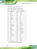
Page 87: ...3 26 NC 7 GND 27 LCD_DIMO 8 LVDSA0 28 LCD_SELB 9 LVDSA0 29 VCC_LCD_AVDD 10 GND 30 GND 11 LVDSA1 31 VLED 12 LVDSA1 32 VLED 13 GND 33 LCD_LR 14 LVDSA2 34 LCD_UD 15 LVDSA2 35 LCD_VGL 16 GND 36 LCD_CABC_E...

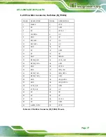
Page 88: ...10 NC 11 REFCLK0 12 NC 13 REFCLK0 14 NC 15 GND 16 NC 17 NC 18 GND 19 NC 20 NC 21 GND 22 PERST 23 MPCIE_RXD 24 VCC3_AUX 25 MPCIE_RXD 26 GND 27 GND 28 VCC1 5 29 GND 30 SMB_CLK 31 MPCIE_TXD 32 SMB_DATA...

Page 89: ...C 13 REFCLK0 14 NC 15 GND 16 NC 17 NC 18 GND 19 NC 20 NC 21 GND 22 PERST 23 MPCIE_RXD 24 VCC3_AUX 25 MPCIE_RXD 26 GND 27 GND 28 VCC1 5 29 GND 30 SMB_CLK 31 MPCIE_TXD 32 SMB_DATA 33 MPCIE_TXD 34 GND 35...

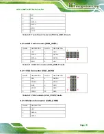
Page 90: ...D1 Pinouts 6 2 7 Speaker Connector CN3 PIN NO DESCRIPTION 1 AUD_OUTL 2 AUD_OUTL 3 AUD_OUTR 4 AUD_OUTR Table 6 8 Speaker Connector CN3 Pinouts 6 2 8 SPI Flash Connector JSPI1 PIN NO DESCRIPTION 1 1 8V...

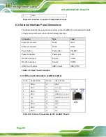
Page 91: ...DESCRIPTION 1 5V 2 GND 3 DATA4 4 DATA3 5 DATA4 6 DATA3 7 GND 8 5V 7 1 8 2 Table 6 11 USB 2 0 Connector HUB_USB1 Pinouts 6 2 11 VGA Connector VGA_CON1 PIN NO DESCRIPTION PIN NO DESCRIPTION 1 RED 2 DDCD...

Page 92: ...LAN1 Ethernet connector RJ 45 LAN2 Power button Push button PB_SW1 Power connector Power jack CN5 RS 232 serial port D sub 9 COM1 RS 232 serial port D sub 9 COM2 USB 3 0 connectors USB 3 0 port USB_CO...

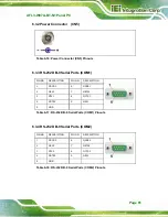
Page 93: ...O DESCRIPTION PIN NO DESCRIPTION 1 NDCD1 6 NDSR1 2 NRX1 7 NRTS1 3 NTX1 8 NCTS1 4 NDTR1 9 NRI1 5 GND Table 6 17 RS 232 DB 9 Serial Ports COM1 Pinouts 6 3 4 RS 232 DB 9 Serial Ports COM2 PIN NO DESCRIPT...

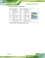
Page 94: ...USB3_PWR1 10 USB3_PWR2 2 USB2P0_DM1_L 11 USB2P0_DM2_L 3 USB2P0_DP1_L 12 USB2P0_DP2_L 4 GND 13 GND 5 USB3P0_RXDN1_L 14 USB3P0_RXDN2_L 6 USB3P0_RXDP1_L 15 USB3P0_RXDP2_L 7 GND 16 GND 8 USB3P0_TXDN1_C_L...

Page 95: ...AFL3 W07A BT N1 Panel PC Page 83 A Safety Precautions Appendix A...

Page 96: ...r the AFL3 W07A BT N1 is being installed moved or modified Do not apply voltage levels that exceed the specified voltage range Doing so may cause fire and or an electrical shock Electric shocks can oc...

Page 97: ...ed the following anti static precautions are strictly adhered to Wear an anti static wristband Wearing a simple anti static wristband can help to prevent ESD from damaging any electrical component Sel...

Page 98: ...and electronic products carrying the mark left must be disposed of separately from normal household waste This includes monitors and electrical accessories such as signal cables or power cords When yo...

Page 99: ...Tools Some components in the AFL3 W07A BT N1 may only be cleaned using a product specifically designed for the purpose In such case the product will be explicitly mentioned in the cleaning tips Below...

Page 100: ...AFL3 W07A BT N1 Panel PC Page 88 B BIOS Menu Options Appendix B...

Page 101: ...ed 51 Intel Virtualization Technology Enabled 52 EIST Enabled 52 Serial ATA SATA Enabled 53 SATA Mode AHCI Mode 53 USB Devices 54 Legacy USB Support Enabled 54 DVMT Pre Allocated 256M 57 DVMT Total Gf...

Page 102: ...AFL3 W07A BT N1 Panel PC Page 90 Discard Changes and Reset 64 Restore Defaults 64 Save as User Defaults 65 Restore User Defaults 65...

Page 103: ...AFL3 W07A BT N1 Panel PC Page 91 Appendix C C Watchdog Timer...

Page 104: ...15H AH 6FH Sub function AL 2 Sets the Watchdog Timer s period BL Time out value Its unit second is dependent on the item Watchdog Timer unit select in CMOS setup Table C 1 AH 6FH Sub function Call sub...

Page 105: ...s not deactivated the system will automatically restart after the Timer has finished its countdown EXAMPLE PROGRAM INITIAL TIMER PERIOD COUNTER W_LOOP MOV AX 6F02H setting the time out value MOV BL 30...

Page 106: ...AFL3 W07A BT N1 Panel PC Page 94 D Hazardous Materials Disclosure Appendix D...

Page 107: ...presences of small quantities of certain materials in the product and is applicable to China RoHS only A label will be placed on each product to indicate the estimated Environmentally Friendly Use Pe...

Page 108: ...it Board O O O O O O Metal Fasteners O O O O O O Cable Assembly O O O O O O Fan Assembly O O O O O O Power Supply Assemblies O O O O O O Battery O O O O O O O This toxic or hazardous substance is cont...

Page 109: ...AFL3 W07A BT N1 Panel PC Page 97 RoHS RoHS Pb Hg Cd CR VI PBB PBDE O O O O O O O O O O O O O O O O O O O O O O O O O O O O O O O O O O O O O O O O O O O O O O O O O SJ T11363 2006 X SJ T11363 2006...

Reviews: